Vehicle brake device

a brake device and vehicle technology, applied in the direction of electric devices, brake components, braking systems, etc., can solve the problems of large size and weight of the vehicle hydraulic brake device itself, complicated construction and cost increase, and limited space for regenerative brake force, etc., to achieve small dimension and light weight

Inactive Publication Date: 2005-12-08
ADVICS CO LTD
View PDF11 Cites 138 Cited by
  • Summary
  • Abstract
  • Description
  • Claims
  • Application Information

AI Technical Summary

Benefits of technology

[0012] Accordingly, it is a primary object of the present invention in one aspect to provide an improved vehicle brake device capable of being made small in dimension and light in weight and capable of making the hydraulic brake force of a hydraulic brake device compensate for the lack of the brake force due to the variation which a regenerative brake device has in its regenerative brake force.
[0013] It is an object of the present invention in another or second aspect to provide an improved vehicle brake device capable of improving the ratio of the regenerative brake force in serving for the target brake force set in dependence on the braking manipulation force even where the same is in a low range and also capable of improving the feeling about the delay of brake to work upon sudden braking.
[0014] A further object of the present invention in a third aspect is to provide an improved vehicle brake device capable of achieving a high efficiency of regeneration and a high fuel efficiency by positively utilizing a regenerative brake force in a low stepping force range which extends from a time point when the brake pedal begins to be stepped to a predetermined state.

Problems solved by technology

However, it is required to provide the fluid pressure generating device 12 such as accumulators, the pressure regulating valve 16, the auxiliary fluid pressure chamber 19 and the like, and there arises a problem that the vehicle hydraulic brake device itself is still large in dimension and heavy.
In addition, the booster for boosting the braking manipulation force has to be additionally provided with the boosting ratio changing mechanism, thereby making the construction complicated and the cost increased.
Thus, there is no room for the regenerative brake force to work for the target vehicle brake force, and this makes it unable to utilize the regenerative brake force positively.
This gives rise to a problem that the regeneration efficiency (i.e., the ratio of the regenerative brake force to the target vehicle brake force) is deteriorated to that extent, thereby resulting in the deterioration of the vehicle fuel efficiency.

Method used


Image

  • Vehicle brake device
  • Vehicle brake device
  • Vehicle brake device

Examples


first embodiment

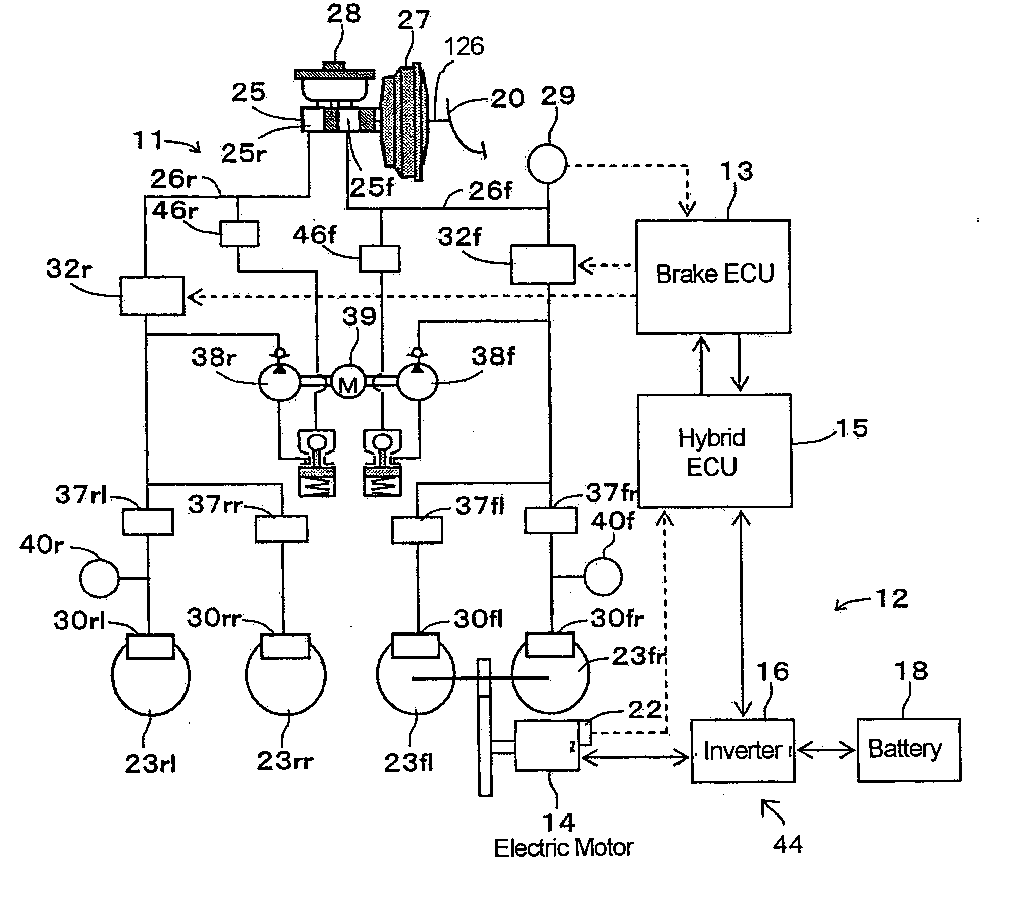
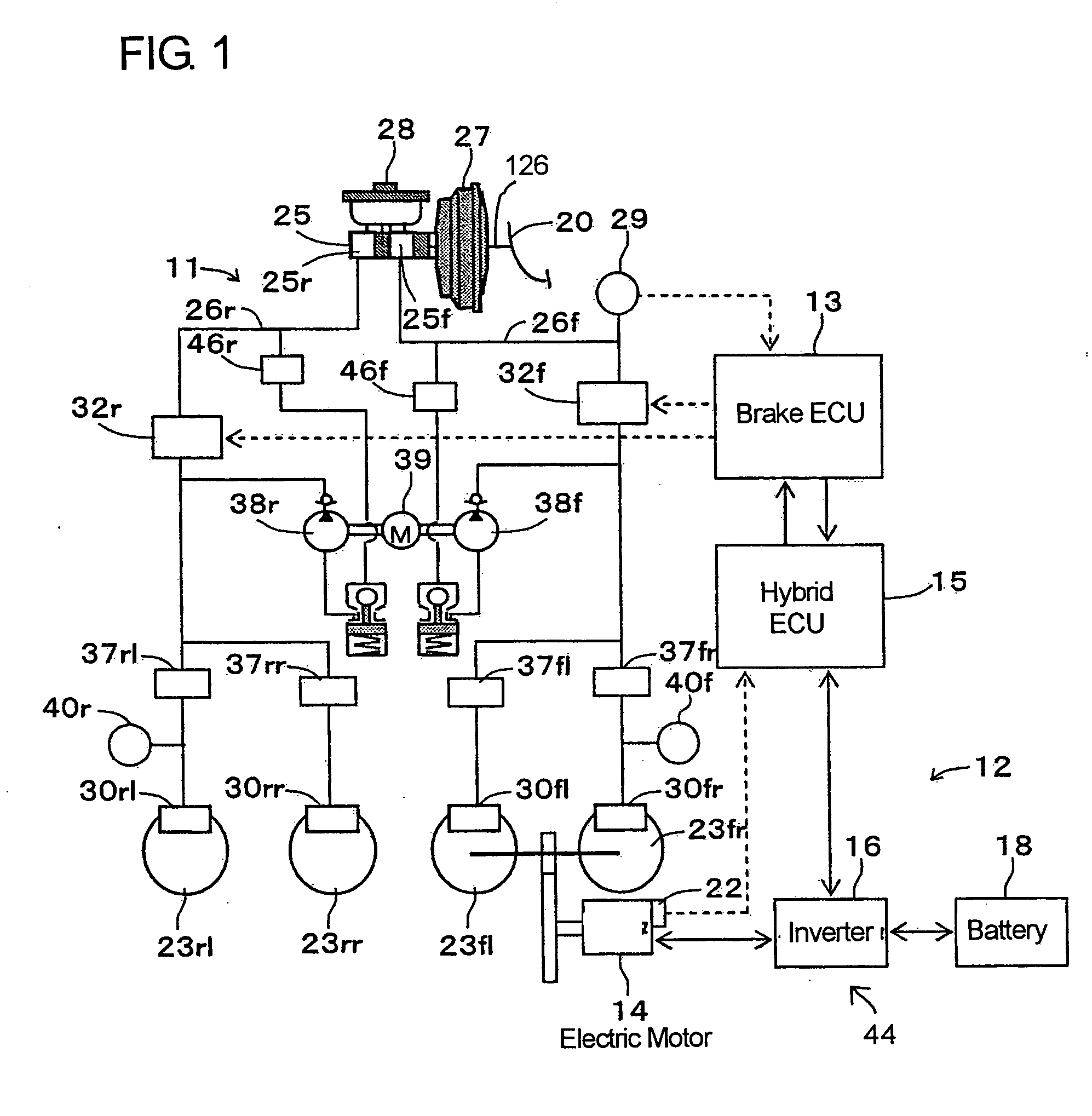
[0048] A vehicle brake device in a first embodiment according to the present invention will be described hereinafter with reference to the accompanying drawings. As shown in FIG. 1, the vehicle brake device is constructed to be applied to a front-drive motor driven car and is provided with a hydraulic brake device 11, a regenerative brake device 12, a brake ECU 13 for cooperatively controlling these devices 11 and 12, and a hybrid ECU 15 for controlling an electric motor 14 which is the drive power source for the motor driven car, through an inverter 16 in dependence on a demand value from the brake ECU 13.

[0049] The hydraulic brake device 11 is capable of applying a base hydraulic brake force to each of the wheels 23 by causing a vacuum booster 27 as a booster device to increase the braking manipulation force which is generated by the braking manipulation or the stepping manipulation on a brake pedal 20 and by applying a base fluid pressure depending on the increased braking manip...

second embodiment

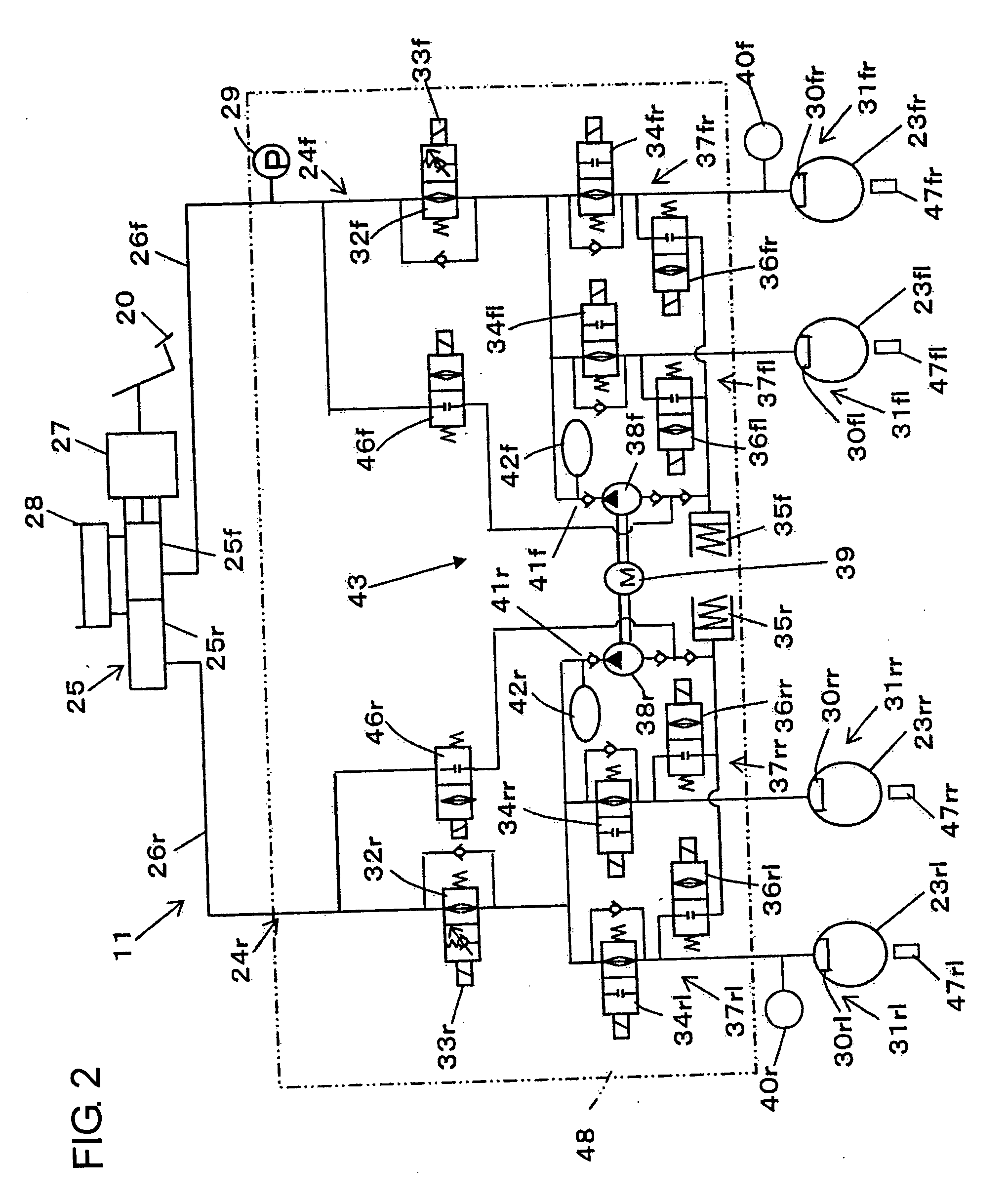
[0096] A second embodiment shown in FIG. 10 differs from the first embodiment in that the control start for the pump drive is made at the same timing as the start of the braking manipulation. The hydraulic circuit arrangement of the hydraulic brake device 11 shown in FIG. 2 is similarly applicable to the second embodiment, and therefore, a flow chart used in the second embodiment will be described with reference to FIG. 2.

[0097] Referring now to FIG. 10, the brake ECU 13 executes a program corresponding to the flow chart at a predetermined minute time interval when an ignition switch (not shown) of the vehicle is in ON state. The brake ECU 13 takes thereinto the master cylinder pressure representing the manipulating state of the brake pedal 20, from the fluid pressure sensor 29 (step S202). Then, at step 204, it is judged whether or not the braking manipulation is being performed, and if the judgment at step 204 is YES, it is further judged at step 206 whether or not the vehicle ha...

third embodiment

[0120] A vehicle brake device in a third embodiment according to the present invention is designed for hybrid vehicles and uses the same system circuit diagram as shown in FIGS. 1 and 2 used in the foregoing first embodiment. Therefore, the third embodiment will be described hereinafter with reference to FIGS. 1 and 2 in addition to FIGS. 11 to 14, wherein description will be directed to the respects different from the foregoing first embodiment for the sake of brevity.

[0121] Referring now to FIGS. 1 and 2, a rotational shaft of the electric motor 14 is always in driving connection with the front left and right wheels 23fl, 23fr through a reduction gear train. The inverter 16 converts the direct current power of the battery 18 to an alternate current power in dependence on control signals supplied from the hybrid ECU 15 to supply the converted alternate current power to the electric motor 14 and also converts the alternate current power generated by the electric motor 14 converts i...


PUM


Abstract

A vehicle brake device is provided with a hydraulic brake device for boosting by a booster device a braking manipulation force generated upon a braking manipulation, for applying a base fluid pressure generated in dependence on the boosted brake manipulation force, to wheel cylinders of wheels so that a base hydraulic brake force is generated on the wheels, and for driving a pump to generate and apply a controlled fluid pressure to the wheel cylinders so that a controlled hydraulic brake force is generated on the wheels; braking manipulation state detecting means for detecting the braking manipulation state; a regenerative brake device for causing an electric motor to generate a regenerative brake force corresponding to the braking manipulation state on the wheels driven by the electric motor; variation detecting means for detecting the variation of an actual regenerative brake force actually generated by the regeneration braking device; and brake force compensating means for generating the controlled fluid pressure by driving the pump of the hydraulic brake device so that a controlled hydraulic brake force is generated on the wheels to compensate for the lack of the regenerative brake force due to the variation which is detected by the variation detecting means.

Description

[0001] This application claims priorities under 35 U.S.C. 119 with respect to Japanese Applications No. 2004-170309 filed on Jun. 8, 2004, No. 2004-174401 filed on Jun. 11, 2004, No. 2004-285676 filed on Sep. 30, 2004 and No. 2004-367601 filed on Dec. 20, 2004. BACKGROUND OF THE INVENTION [0002] 1. Field of the Invention [0003] The present invention relates to a vehicle brake device in which a target regenerative brake force to be applied to wheels in dependence on the braking manipulation state is attained by the sum of a hydraulic brake force of a hydraulic brake device and a regenerative brake force of a regenerative brake device. [0004] 2. Discussion of the Related Art [0005] Heretofore, as described in Japanese unexamined, published patent application No. 2002-264795 (hereafter as Patent Document 1), there has been known a vehicle hydraulic brake device which is simplified in construction, inexpensive and suitable for use in an electric car performing a regenerative braking as ...

Claims


Application Information

Patent Timeline
Patent Type & Authority Applications(United States)
IPC IPC(8): B60T8/64B60T13/58B60W10/08B60W10/18B60W30/18
CPCB60L7/26Y02T10/642B60T8/4872B60T13/586B60T2270/604B60T2270/608B60W10/08B60W10/184B60W30/18127B60L3/108B60L7/14B60L11/123B60L11/14B60L11/1861B60L15/2009B60L2210/40B60L2240/12B60L2240/421B60L2240/423B60L2240/461B60L2240/465B60L2250/26Y02T10/7077Y02T10/7044Y02T10/7005Y02T10/705Y02T10/7241Y02T10/7275Y02T10/6217B60T8/38B60L50/61B60L50/16B60L58/12Y02T10/62Y02T10/64Y02T10/70Y02T10/72Y02T10/7072
Inventor MAKI, KAZUYAMATSUURA, MASAHIROSAITO, SHIGERUKOKUBO, KOICHISENGOKU, YUJI
Owner ADVICS CO LTD
Why Eureka
Try Eureka