
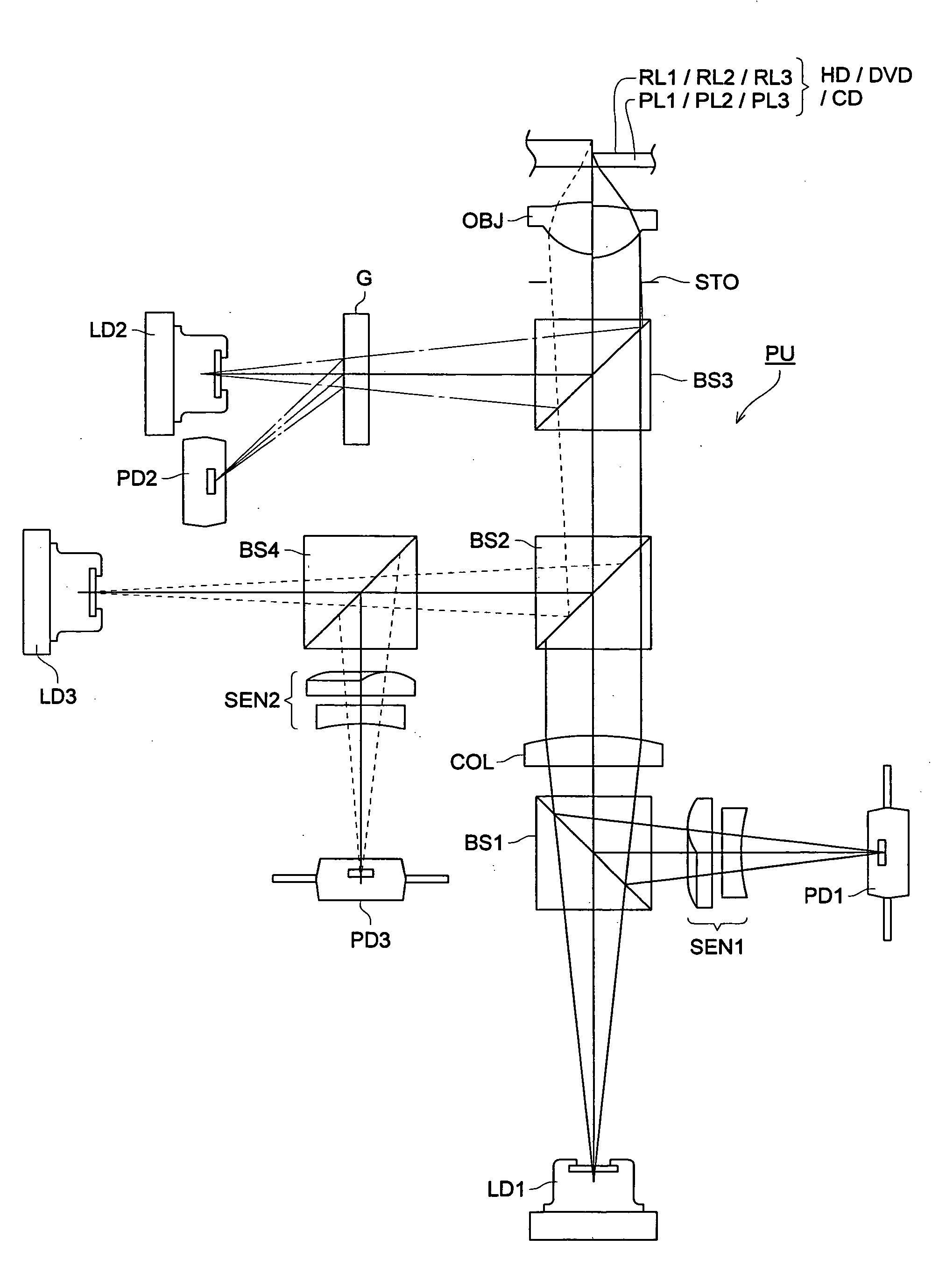
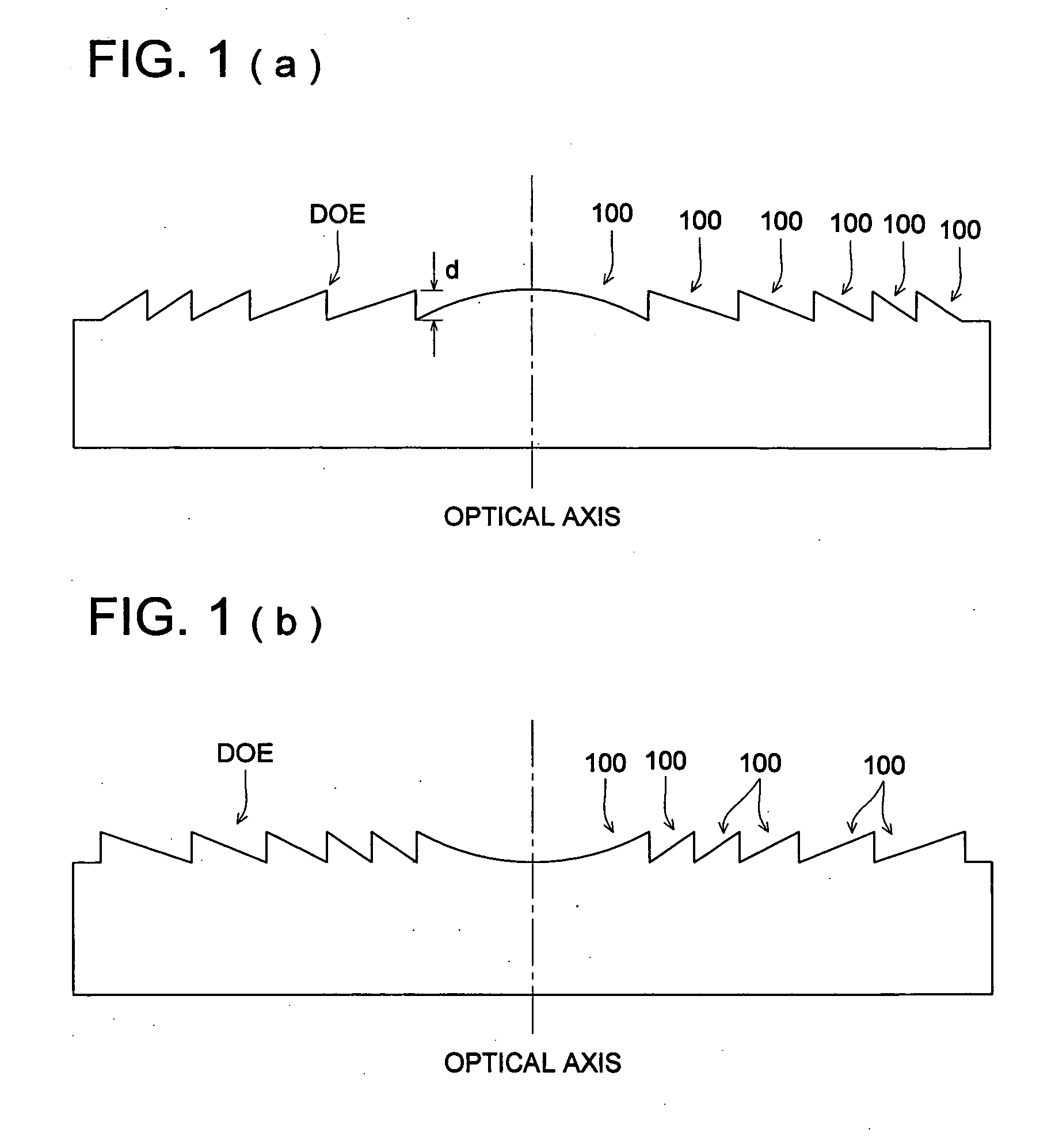
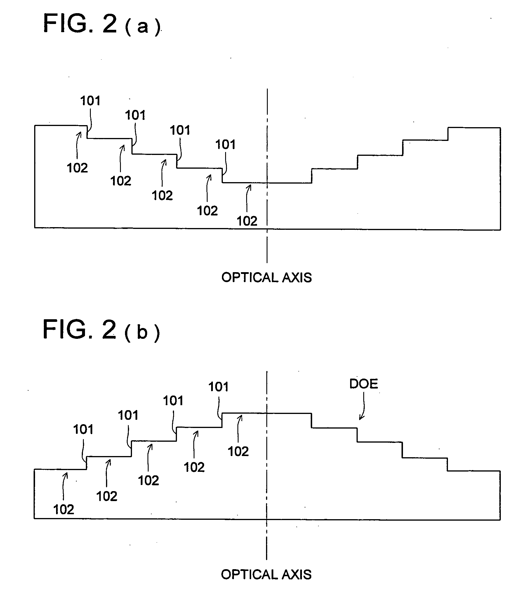
Objective lens and optical pickup apparatus

Inactive Publication Date: 2005-12-08
KONICA MINOLTA OPTO
View PDF36 Cites 11 Cited by
  • Summary
  • Abstract
  • Description
  • Claims
  • Application Information

AI Technical Summary

Benefits of technology

[0010] An object of the invention is backed by consideration of the problems mentioned above, and is to provide an objective lens that is used for reproducing and / or recording of information for at least two types of optical discs including high density discs, and has excellent wavelength characteristics, temperature characteristics and tracking characteristics and to provide an optical pickup apparatus employing this objective lens.

Problems solved by technology

However, if this technology is applied on compatibility for high density discs and conventional discs, the following problem takes place.
The problems is that there is no solution which satisfies both of compatibility and ambient characteristics even when designing with one parameter of wavelength-dependence of diffraction, for the lens compatible for high density discs and conventional discs, while, the wavelength-dependence of the diffraction determined to attain compatibility just satisfies ambient characteristics, in the DVD-CD compatible lens.
In the invention described in Patent Document 1, there arises a problem wherein wavelength characteristics caused by diffraction grow greater, although coma caused by lens shift in the case of tracking is not generated in this method, and wavefront aberration is deteriorated when an oscillation wavelength in a certain lot of lasers is different from that in another lot.

Method used


Image

  • Objective lens and optical pickup apparatus
  • Objective lens and optical pickup apparatus
  • Objective lens and optical pickup apparatus

Examples


example 1

[0109] Table 1 shows lens data of Example 1.

TABLE 1Example 1 Lens dataFocal length of objectivef1 = 3.2 mmf2 = 3.27 mmf3 = 3.27 mmlensNumerical aperture on theNA1: 0.65NA2: 0.65NA3: 0.51image sideDiffraction order number onn1: 3n2: 2n3: 22nd surfaceMagnificationm1: 0m2: 1 / 185.2m3: −1 / 55.6ithdinidinidinisurfaceri(407 nm)(407 nm)(655 nm)(655 nm)(785 nm)(785 nm)0∞−600.00185.001∞0.10.10.1*1 (φ4.16 mm)(φ4.23 mm)(φ3.40 mm)22.021081.900001.5427711.900001.529151.900001.525413−9.548461.751.01.781.01.481.04∞0.61.618690.61.577521.21.570635∞*1: (Aperture)*The symbol di shows a displacement from ith surface to (i + 1)th surface.Aspheric surface dataSecond surfaceAspheric surface coefficientκ−4.4201 × E−1A4−6.6218 × E−4A6−1.4866 × E−3A8+5.2339 × E−4A10−1.0140 × E−4A12+8.5260 × E−6A14−1.1279 × E−6Optical path difference functionB2−2.5983B4−2.8209 × E−1B6−2.7379 × E−1B8+5.2628 × E−2B10−5.2204 × E−3Third surfaceAspheric surface coefficientκ−1.7944 × E+2A4−9.8565 × E−3A6+1.1687 × E−2A8−5.1568 × E−3...

example 2

[0116] Table 2 shows lens data of Example 2.

TABLE 2Example 2 Lens dataFocal length of objectivef1 = 3.2 mmf2 = 3.27 mmf3 = 3.27 mmlensNumerical aperture on theNA1: 0.65NA2: 0.65NA3: 0.51image sideDiffraction order numbern1: 3n2: 2n3: 2on 2nd surfaceMagnificationm1: −1 / 185.2m2: 0m3: −1 / 44.8ithdinidinidinisurfaceri(407 nm)(407 nm)(655 nm)(655 nm)(785 nm)(785 nm)0600.00∞130.001∞0.10.10.1*1 (φ4.18 mm)(φ4.25 mm)(φ3.41 mm)22.024501.900001.5427711.900001.529151.900001.525413−9.521531.761.01.801.01.501.04∞0.61.618690.61.577521.21.570635∞*1: (Aperture diameter)*The symbol di shows a displacement from ith surface to (i + 1)th surface.Aspheric surface dataSecond surfaceAspheric surface coefficientκ−4.4431 × E−1A4−9.1275 × E−4A6−1.4646 × E−3A8+5.2560 × E−4A10−1.0309 × E−4A12+8.1328 × E−6A14−9.6245 × E−7Optical path difference functionB2−2.7376B4−2.9254 × E−1B6−2.7583 × E−1B8+5.3981 × E−2B10−5.3153 × E−3Third surfaceAspheric surface coefficientκ−1.7044 × E+2A4−1.0136 × E−2A6+1.1696 × E−2A8−5.1...

example 3

[0122] Table 3 shows lens data of Example 3.

TABLE 3Example 3 Lens dataFocal length of objectivef1 = 3.1 mmf2 = 3.23 mmf3 = 3.23 mmlensNumerical aperture on theNA1: 0.65NA2: 0.65NA3: 0.51image sideOptical systemm1 = 1 / 28.4m2 = 0m3 = −1 / 35.6magnificationithdinidinidinisurfaceri(407 nm)(407 nm)(655 nm)(655 nm)(785 nm)(785 nm)0−85∞117.841∞0.10.10.0*1 (φ5.10 mm)(φ5.10 mm)(φ5.10 mm)21.97491.761.55981.761.54071.761.5372 2′1.9549−0.003181.5598−0.003181.5407−0.003181.53723−16.87661.571.01.791.01.491.04∞0.61.6190.61.5781.21.5715∞*1: (Aperturediameter)*The symbol di shows displacement from ith surface to (i + 1)th surface.Aspheric surface dataSecond surface (0.00 mm ≦ h ≦ 1.923 mm)Aspheric surface coefficientκ−5.3412E−01A4−3.6678E−04A69.6666E−04A8−1.3357E−04A10−6.7434E−05A122.5231E−05A14−3.3947E−06Optical path difference function (HD DVD: Second orderDVD: First order CD: First order Blazed wavelength395 nm)B2−4.1750E−03B4−7.7289E−04B62.6030E−04B8−1.1363E−04B101.3297E−052′th surface (1.923 mm...


PUM


Abstract

The present invention includes relates to an objective lens used for reproducing and / or recording of information for at least two types of optical discs including high density discs, and has excellent wavelength characteristics, temperature characteristics and tracking characteristics and to provide an optical pickup apparatus employing this objective lens. An objective lens according to the present invention is used for an optical pickup apparatus at least reproducing and / or recording information for a first optical disc having a protective substrate with a thickness t1 and a second optical disc having a protective substrate with a thickness t2 (0.8×t1≦t2). Each of the light fluxes with a wavelength λ1 and a wavelength λ2 enters into the objective lens and a diffractive structure is formed on the at least one optical surface of the objective lens, signs and values of an optical system magnification of the objective lens m1 and m2 for the light fluxes with wavelength λ1 and λ2 respectively are different each other, and the diffractive structure has a positive diffractive action.

Description

BACKGROUND OF THE INVENTION [0001] The present invention relates to an objective lens and an optical pickup apparatus. [0002] In recent years, a trend toward a short wavelength of a laser light source used as a light source for reproducing information recorded on an optical disc or for recording information on an optical disc has been advanced, in an optical pickup apparatus, and there have been put to practical use laser light sources with a wavelength of 405 nm such as, for example, a violet semiconductor laser and a violet SHG laser wherein generation of the second harmonic is used for wavelength conversion of an infra-red semiconductor laser. [0003] If these violet laser light sources are used, information in 15-20 GB can be recorded for an optical disc having a diameter of 12 cm, when using an objective lens with a numerical aperture (NA) identical to that of a digital versatile disc (which will be abbreviated as DVD, hereafter), and when NA of an objective lens is enhanced to ...

Claims


Application Information

Patent Timeline
IPC IPC(8): G02B27/00G02B5/18G02B3/10G02B13/14G11B7/135G11B7/00G02B13/18G11B7/1353G11B7/1374G11B7/1392
CPCG02B13/146G02B27/0037G02B27/4283G02B27/4288G11B7/1353G11B7/1374G11B7/13922G11B2007/0006G02B13/00G02B5/18
Inventor IKENAKA, KIYONO
Owner KONICA MINOLTA OPTO
Features
  • Generate Ideas
  • Intellectual Property
  • Life Sciences
  • Materials
  • Tech Scout
  • Unparalleled Data Quality
  • Higher Quality Content
  • 60% Fewer Hallucinations
Learn More