Fluid vessel

a technology of flue gas and cylinder, which is applied in the field of flue gas vessels, can solve the problems of inability to negligible safety matters, difficult to apply flue gas uniformly with a selected thickness, and forming unwanted spaces around the periphery, etc., and achieves convenient operation, good reliability, and less trouble.

Inactive Publication Date: 2005-12-08
HITACHT MAXELL LTD
View PDF6 Cites 80 Cited by
  • Summary
  • Abstract
  • Description
  • Claims
  • Application Information

AI Technical Summary

Benefits of technology

[0062] As to the fluid vessel of the first acpect according to the present invention, the double-faced adhesive sheet as the bonding element bonds the cover plate to the base member so as to join them. In addition, since the double-faced adhesive sheet has the opening which has been formed beforehand so as to correspond to the profile of the opening surface of the channel formed in the base member, the space between the peripheral portion of the opening of the channel and the cover plate is occupied by the inner peripheral wall portion which defines the opening of the double-faced adhesive sheet in the fluid vessel in which the cover plate has been bonded to the base plate.
[0066] the reaction of the adhesive with such fluid. Further, by the correspondence of the profile of the opening surface of the channel to the opening profile of the double-faced adhesive sheet, the problem in the formation of the unwanted space around the opening surface of the channel may be eliminated.
[0067] Thus, in the fluid vessel of the firs aspect according to the present invention, the cover plate and the base member are bonded together, and the channel has a predetermined volume and the adverse effect of the bonding element on the fluid (such as an analyte) can be minimized, so that the fluid vessel (for example, the reaction vessel) having a good reliability is provided. Since the cover plate is able to bonded to the base member appropriately by means of the double-faced adhesive sheet, the integration of the base member and the cover plate can be carried out conveniently with less trouble, so that the fluid vessel may be produced less expensively even though the number of the fluid vessel produced in one lot is small.
[0068] Generally, a plastic sheet is less bendable and more elastic when compared with paper, a non-woven fabric or the like. Thus, when a flat and smooth plastic sheet which is excellent in its chemical resistance is used as the sheet substrate for the double-faced adhesive sheet, handling of the double-faced adhesive sheet is more readily upon the bonding operati

Problems solved by technology

When the cover plate is bonded to the base member, it is difficult to apply the adhesive uniformly with a selected thickness.
What is problem is that the adhesive which has been already applied cannot be spread sufficiently between the cover plate and the base member when the cover plate is placed on the base member to join them, so that an unwanted space may be formed around a periphery of an opening of the channel.
However, the bonding manner with using the solvent may produce a space in the closed channel is contaminated with residual of the solvent, and the residual has to be removed by an additional operation such as washing.
In addition, when the solvent is a toxic one, a safety matter cannot be negligible.
When the base member and the cover plate are brought integral by means of the ultrasonic welding, there is a possibility that dusts (or melt droplets) formed by the ultrasound are confined in the space of the channel, so that a

Method used


Image

  • Fluid vessel
  • Fluid vessel
  • Fluid vessel

Examples


example 1

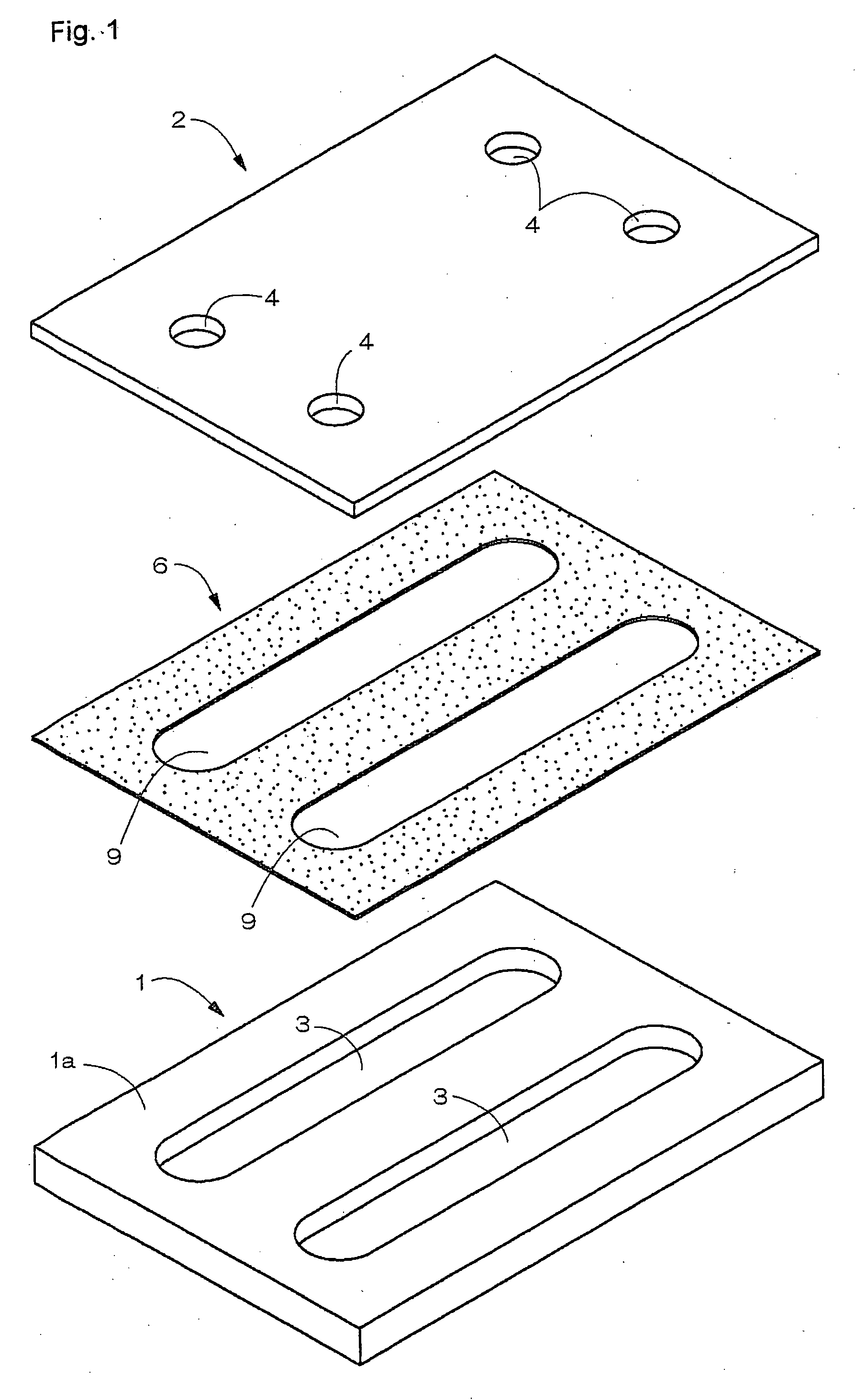
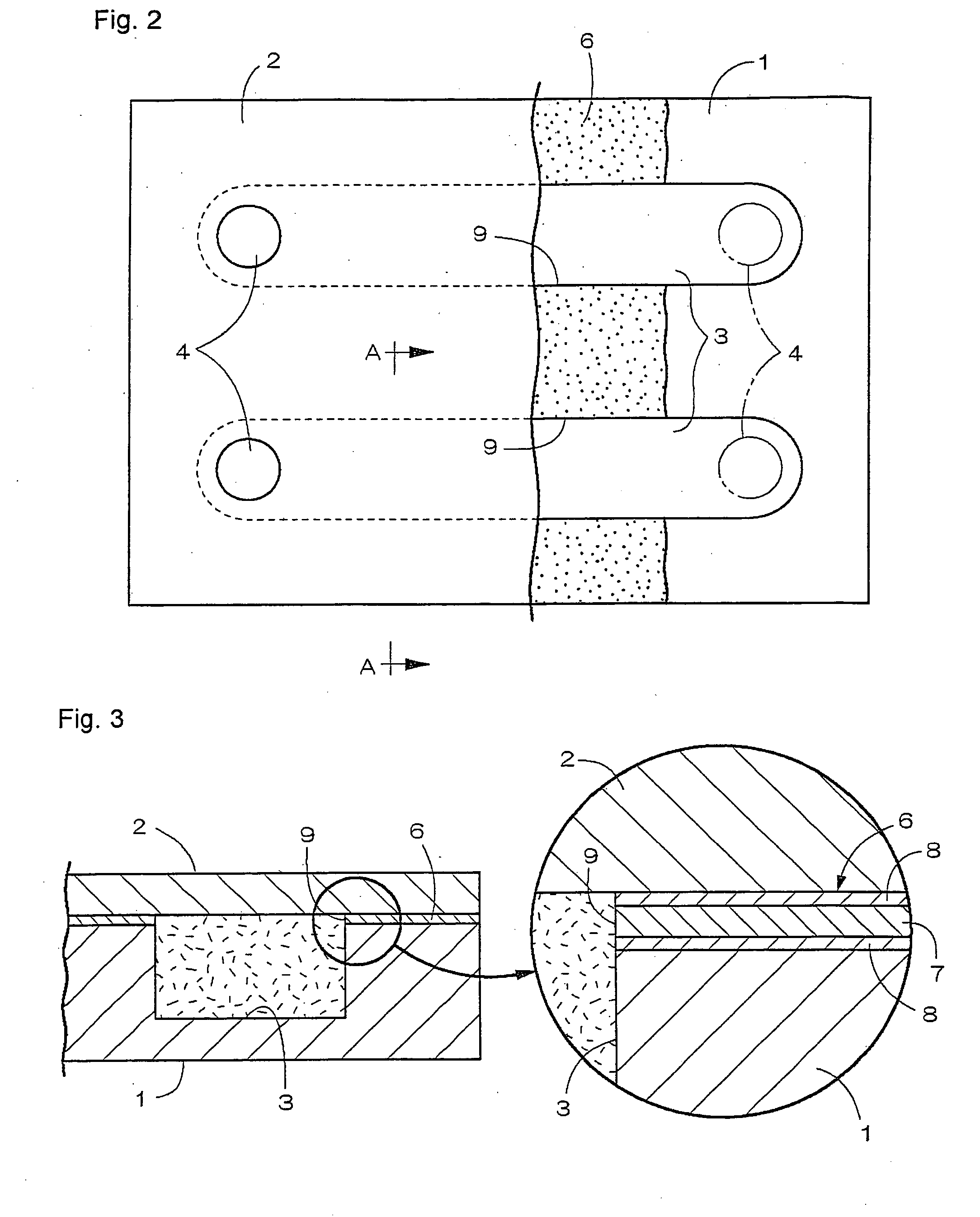
[0109] With reference to FIGS. 1 to 3, Example 1 of the fluid vessel (for example, a reaction vessel) according to the present invention which corresponds to the first aspect will be explained. It is noted that FIG. 1 schematically shows a perspective view of the fluid vessel in its exploded state, FIG. 2 schematically shows a plan view of the fluid vessel while a part thereof is cut away, and FIG. 3 schematically shows a cross-sectional view of a portion of the fluid vessel along a line A-A in FIG. 2. The fluid vessel of Example 1 comprises a base member 1 and a cover plate 2 which is bonded to the base member 1.

[0110] The base member 1 is formed into a plate form which defines a planar area and of which thickness dimension is relatively smaller than the other dimensions. The base member 1 has an elongated rectangular shape in its projected planar view. The base member 1 may be formed by using for example a borosilicate glass, a quartz glass or a resin such as a polydimetylsiloxan...

example 2

[0122] With reference to FIGS. 4 to 6, Example 2 of the fluid vessel (for example, a reaction vessel) according to the present invention which corresponds to the second aspect will be explained. It is noted that FIG. 4 schematically shows a perspective view of the fluid vessel in its exploded state, FIG. 5 schematically shows a plan view of a portion of the fluid vessel, and FIG. 6 schematically shows a perspective view of a stencil plate which is used for the formation of an adhesive layer. In Example 2, since the base member 1 and the cover plate 2 which is boned to the base member 1 are substantially the same as those in Example 1, the same reference numbers as in Example 1 are used to indicate the same members as in Example 1, and explanations of them are omitted here. It is noted that a whole of the cover plate 2 is made of a transparent material for the purpose of passing UV as explained below.

[0123] In FIGS. 4 and 5, upon the production of the fluid vessel, the base member 1...

example 3

[0130] With reference to FIGS. 7 to 10, Example 3 of the fluid vessel (for example, a reaction vessel) according to the present invention which corresponds to the second aspect will be explained. It is noted that FIG. 7 schematically shows a perspective view of the fluid vessel in its exploded state, FIG. 8 schematically shows a plan view of the fluid vessel while a part thereof is cut away, and FIG. 9 schematically shows a cross sectional view of a portion of the fluid vessel (along the line B-B in FIG. 8), and FIG. 10 schematically shows in a cross-sectional view how to carry out spot-welding. In Example 3, since the base member 1 and the cover plate 2 which is boned to the base member 1 are substantially the same as those in Examples 1 and 2, the same reference numbers as in the Examples are used to indicate the same members as in the Examples, and explanations of them are omitted here. It is noted that each of the base member 1 and the cover plate 2 is a molded article of a ther...


PUM

PropertyMeasurementUnit
Shapeaaaaaaaaaa
Adhesivityaaaaaaaaaa
Transparencyaaaaaaaaaa

Abstract

A fluid vessel includes a base member in the form of a plate of which one surface has a concave channel and a cover plate which is bonded to the base plate so as to close an opening surface of the channel. The base member and the cover plate are bonded through a double-faced adhesive sheet. The double-faced adhesive sheet has an opening which corresponds to a formation pattern of the channel. The double-faced adhesive sheet includes a flat and smooth sheet substrate which is made of a plastic sheet having a chemical resistance as well as adhesive layers which are laminated onto both surfaces of the sheet substrate. In a state in which the cover plate is bonded to the base member, a space between the cover plate and a periphery of the channel opening is filled with an inner peripheral wall portion which defines the opening of the double-faced adhesive sheet.

Description

CROSS-REFERENCE TO RELATED APPLICATIONS [0001] The present application claims priorities under the Paris Convention based on Japanese Patent Application No. 2004-118724 (filing date: Apr. 14, 2004, title: fluid device) Japanese Patent Application No. 2004-118725 (filing date: Apr. 14, 2004, title: fluid device) and Japanese Patent Application No. 2004-180467 (filing date: Jun. 18, 2004, title: production method of fluid device), and the contents of those applications are incorporated herein by reference in their entirety. BACK GROUND OF THE INVENTION [0002] 1. Field of the Invention [0003] The present invention relates to a fluid vessel which is used to carry out for example a medical analysis wherein an analyte is subjected to absorption and purification for the DNA analysis, a reaction of a chemical, and an analysis of a synthesized chemical. When a reaction of a fluid is carried out in such fluid vessel, the fluid vessel according to the present invention may be referred to as a ...

Claims


Application Information

Patent Timeline
IPC IPC(8): G01N15/06G01N35/00B01L3/00C12M1/34
CPCB01L3/502707B01L2200/0689B01L2200/12B01L2300/0825B01L2300/0887B01L2400/0406B29C65/02B29C65/08B29C65/5057B29C66/21B29C66/30221B29L2031/756G01N2035/00108B29C65/00B29C65/5021B29C65/4825B29C65/4845B29C66/8322B29C66/53461B29C66/1122B29K2995/0027
Inventor HORITA, TAKASHI
Owner HITACHT MAXELL LTD
Why Eureka
Try Eureka