Transdermal delivery of therapeutic agent

a technology of therapeutic agents and transdermal delivery, which is applied in the field of medical devices, can solve the problems and achieve the effect of painless delivery of therapeutic agents

Inactive Publication Date: 2005-12-08
LYNNTECH
View PDF19 Cites 69 Cited by
  • Summary
  • Abstract
  • Description
  • Claims
  • Application Information

AI Technical Summary

Benefits of technology

[0016] The microprojections are adapted to provide perforation of the epidermis to a depth of between about 50 μm and about 150 μm. Preferably, the microprojections are adapted to transiently perforate the epidermis to a depth greater than the thickness of a stratum corneum layer of the epidermis but less than a depth of sensory nerve ending locations. This...

Problems solved by technology

This provides the desired passages cut through the stratum corneum but does not cut deeply e...

Method used


Image

  • Transdermal delivery of therapeutic agent
  • Transdermal delivery of therapeutic agent
  • Transdermal delivery of therapeutic agent

Examples


example 1

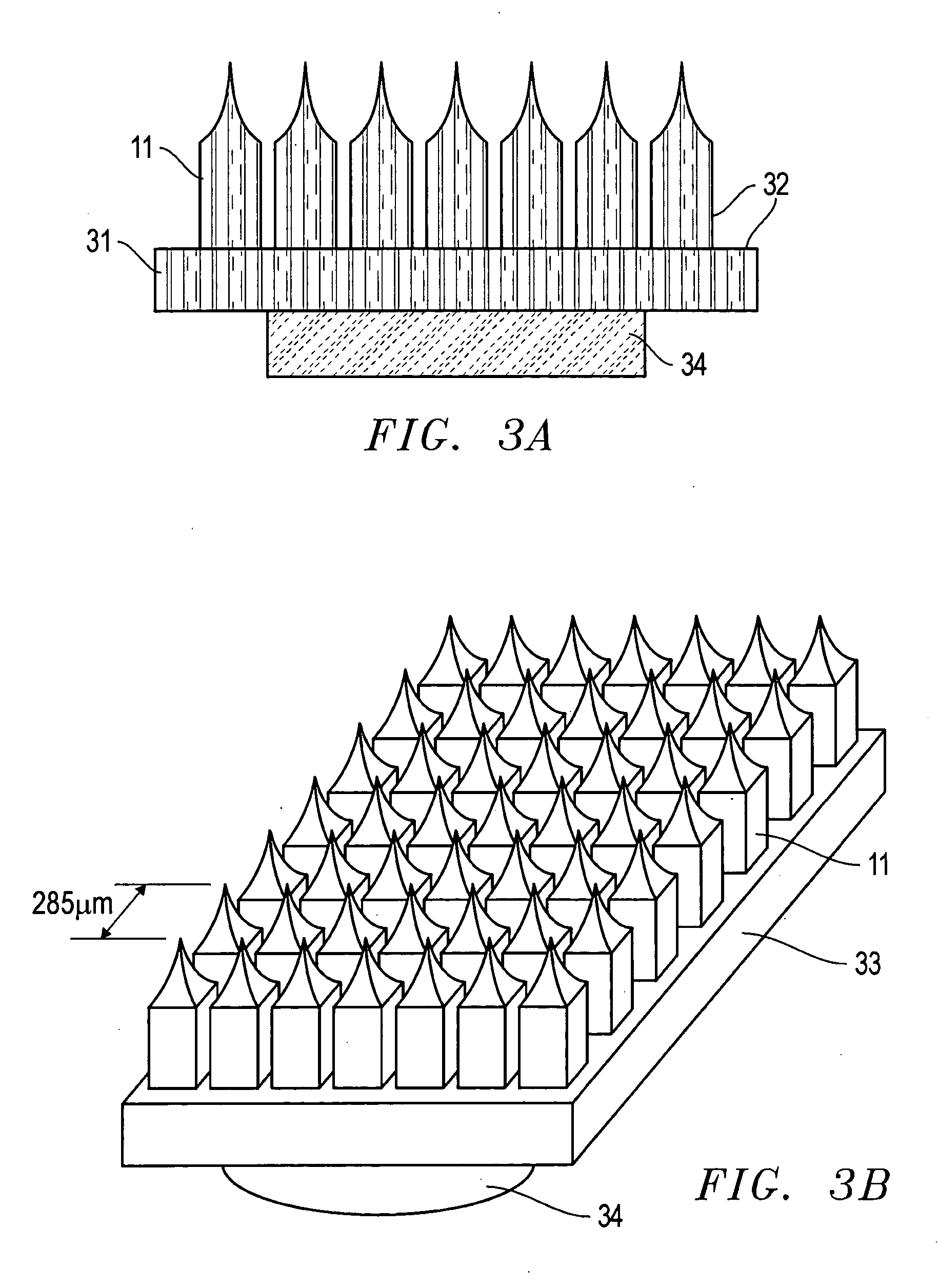
[0058] Microprojections were prepared using the following method. A small glass vial, having a diameter of about 2.5 cm, was filled with a solution used for electroetching wire into the microprojections. The vial was then closed with a plastic cap containing a septum. The solution used for electroetching depends upon the type of wire used for making the microprojections. For tungsten microprojections, the solution used was 0.1 M NaOH. For platinum microprojections, the solution used was saturated NaNO2 solution. For gold microprojections, the solution used contained 10 g KCN and 5 g KOH per 40 mL of water.

[0059] Three stainless steel needles were inserted through the septum so that the ends were about 5 mm above the solution level in the vial. A length of wire about 5 cm in length and having a thickness of about 0.25 mm, was inserted into the solution through the first needle to a depth of about 2 mm. A second wire was inserted through the second needle and immersed in the solution...

example 2

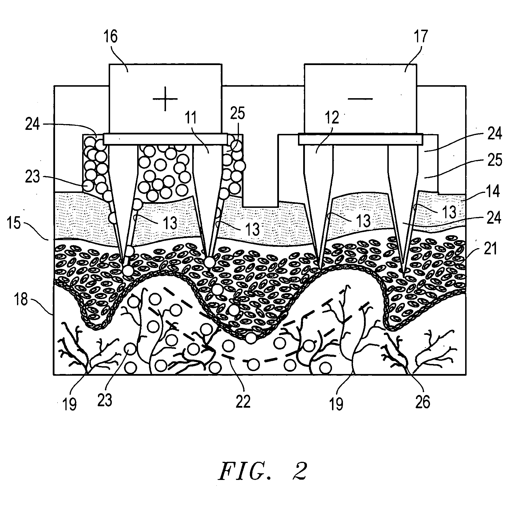
[0061] A sample of pig's skin taken from a pig's foot was placed on a test cell sandwiched between the lower compartment and the top of the cell. The lower compartment of the cell was filled with 0.1 M phosphate buffer. A set of two arrays of conductive gold microprojections, each array having seven microprojections, was slowly moved towards the skin sample while measuring the resistance between the arrays. When the measured resistance dropped sharply from an open circuit reading to about 800 MΩ, the microprojections were known to be in contact with the skin sample and the reading on the micrometer was recorded as the “zero” location from which a precise penetration depth could be measured.

[0062] The arrays of microprojections were then raised above the skin sample and a suspension of microspheres in phosphate buffer was transferred into two compartments of the top portion of the cell. Typically, a 0.1 mL of suspension containing 10 mg of microspheres was used in each compartment. ...


PUM

PropertyMeasurementUnit
Timeaaaaaaaaaa
Timeaaaaaaaaaa
Diameteraaaaaaaaaa

Abstract

A device for the transdermal delivery of a therapeutic agent to a biological subject that includes a first electrode comprising a first array of electrically conductive microprojections for providing electrical communication through a skin portion of the subject to a second electrode comprising a second array of electrically conductive microprojections. Additionally, a reservoir for holding the therapeutic agent surrounding the first electrode and a pulse generator for providing an exponential decay pulse between the first and second electrodes may be provided. A method includes the steps of piercing a stratum corneum layer of skin with two arrays of conductive microprojections, encapsulating the therapeutic agent into biocompatible charged carriers, surrounding the conductive microprojections with the therapeutic agent, generating an exponential decay pulse between the two arrays of conductive microprojections to create a non-uniform electrical field and electrokinetically driving the therapeutic agent through the stratum corneum layer of skin.

Description

BACKGROUND OF THE INVENTION [0001] 1. Field of the Invention [0002] The present invention relates to medical devices, and more specifically, to an apparatus and method for transdermal delivery of pharmaceuticals. [0003] 2. Description of the Related Art [0004] Common methods for administering therapeutic molecules to treat illnesses or injuries to a patient include the use of hypodermic needles and oral ingestion. These methods have limitations. Delivery by oral ingestion or injection by hypodermic syringe can cause drug concentrations in the body to fluctuate between high and low values, whereas a sustained or continuous delivery is desirable. Hypodermic needle delivery is very unpopular with patients, who are often reluctant to perform this procedure on themselves. Furthermore, safe handling and disposal of the biohazardous hypodermic needles is difficult. [0005] Oral administration of drugs remains the most common method of drug delivery because the cells lining the intestine ten...

Claims


Application Information

Patent Timeline
IPC IPC(8): A61K9/00A61K9/06A61K9/14A61K9/16A61N1/30A61N1/32
CPCA61K9/0009A61K9/0021A61K9/06A61K9/16A61M37/0015A61M2037/0023A61N1/306A61N1/325
Inventor KWIATKOWSKI, KRZYSZTOF C.HAYES, RYAN T.MAGNUSON, JAMES W.GILETTO, ANTHONY
Owner LYNNTECH
Why Eureka
Try Eureka