Method and structure for thin film photovoltaic materials using semiconductor materials

a technology of semiconductor materials and photovoltaic materials, applied in the field of photovoltaic materials, can solve the problems of reducing the efficiency of photovoltaic materials, and reducing the cost of photovoltaic materials, so as to improve processing efficiency, facilitate use, and improve the effect of conversion efficiency

Active Publication Date: 2007-11-15
CM MFG
View PDF100 Cites 156 Cited by
  • Summary
  • Abstract
  • Description
  • Claims
  • Application Information

AI Technical Summary

Benefits of technology

[0024] Depending upon the specific embodiment, one or more of these features may also be included. The present technique provides an easy to use process that relies upon conventional technology that is nanotechnology based. Such nanotechnology based materials and process lead to higher conversion efficiencies and improved processing according to a specific embodiment. In some embodiments, the method may provide higher efficiencies in converting sunlight into electrical power. Depending upon the embodiment, the efficiency can be about 10 percent or 20 percent or greater for the resulting solar cell according to the present invention. Additionally, the method

Problems solved by technology

Unfortunately, petrochemical energy is limited and essentially fixed based upon the amount available on the planet Earth.
Additionally, as more human beings begin to drive and use petrochemicals, it is becoming a rather scarce resource, which will eventually run out over time.
Although solar energy is clean and has been successful to a point, there are still many limitations before it becomes widely used throughout the world.
Crys

Method used


Image

  • Method and structure for thin film photovoltaic materials using semiconductor materials
  • Method and structure for thin film photovoltaic materials using semiconductor materials
  • Method and structure for thin film photovoltaic materials using semiconductor materials

Examples


example 1

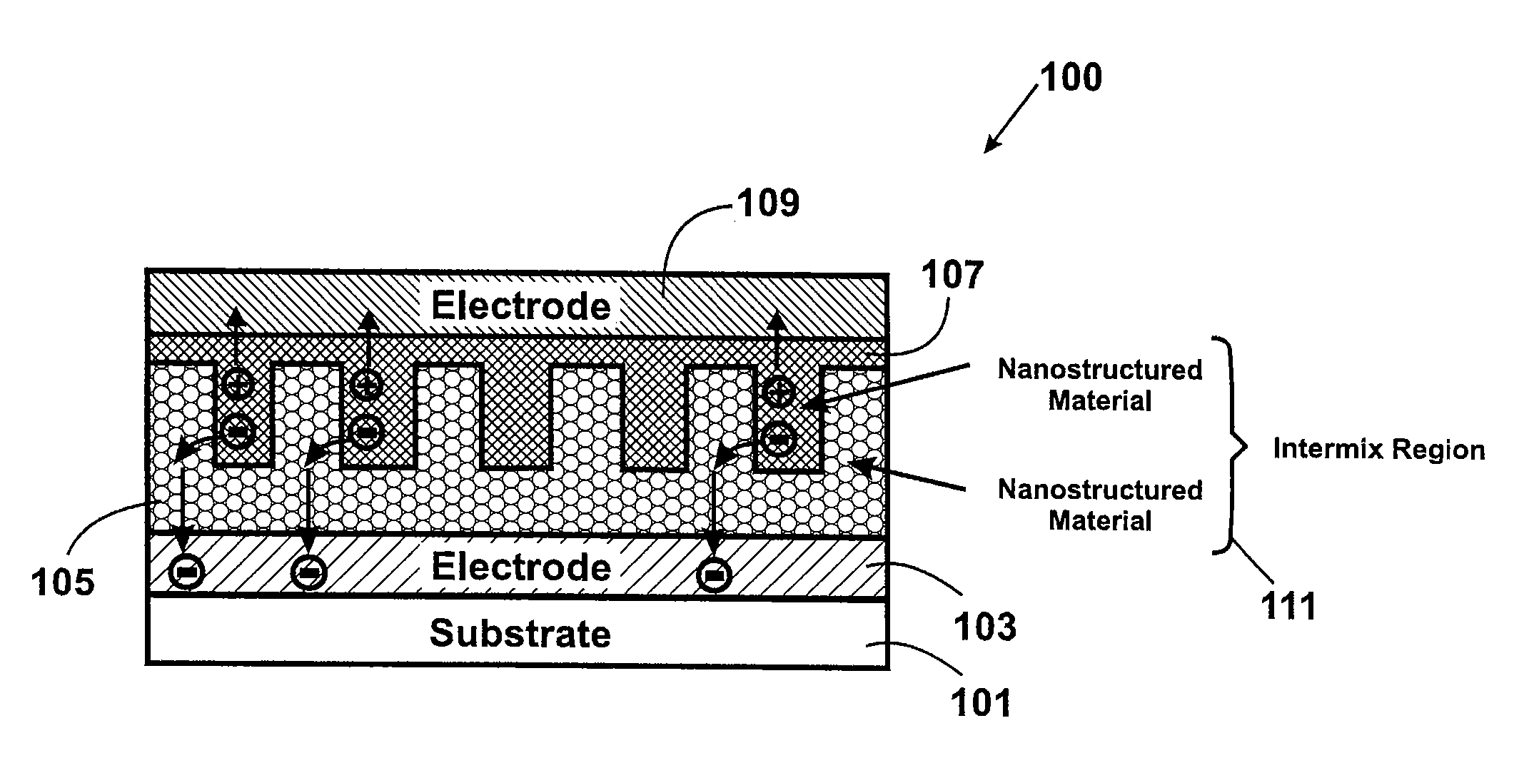
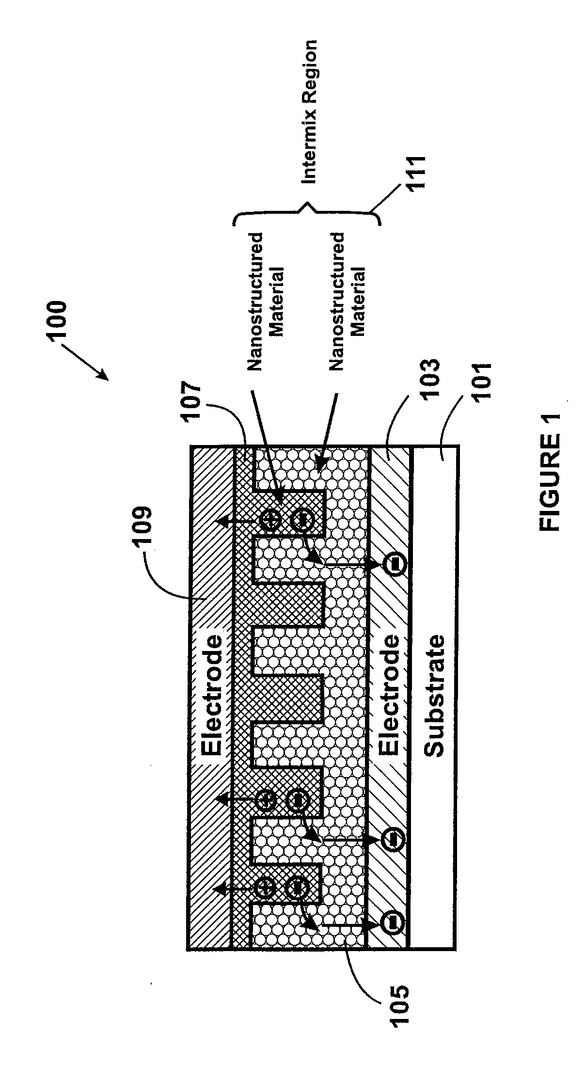
[0385] On a substrate, which can be any optically clear material such as glasses, fused silica, plastic, etc., a transparent conducting electrode (TCE) is deposited, which can be performed with a variety of vacuum methods such as sputtering, evaporation, and solution deposition methods. Examples of TCEs are indium tin oxide (ITO), zinc oxide doped with Al (ZnO:Al), and tin oxide doped with fluorine (SnO2:F). In these examples, we use ZnO:Al.

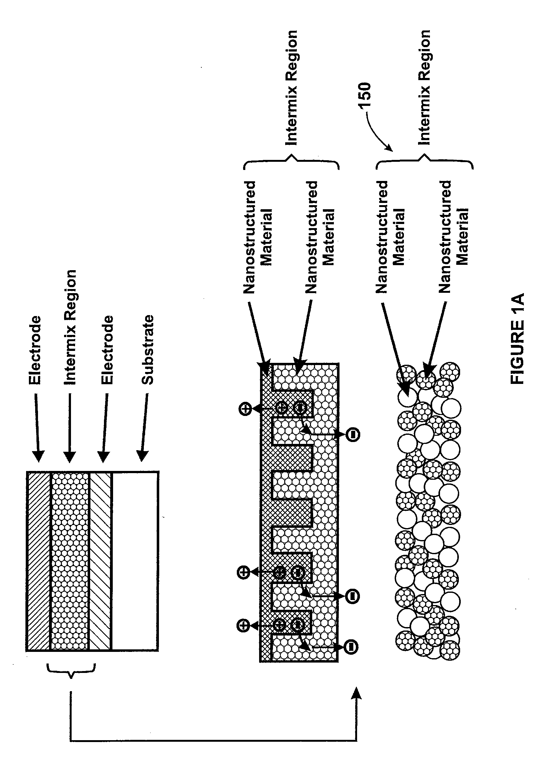
[0386] A layer of nanoparticles (NPs) of a first material is then deposited on the TCE. The thickness of this film can range from about 50 nm to about 1000 nm. This is performed using a colloidal suspension of the NPs and with various types of solution deposition processes such as spin coating, spraying, ink jet printing, dipping, doctor blading, electrophoresis, electrochemical deposition, etc. The first material deposited can be metal oxides such as ZnO, TiO2, SnO2, WO3, Fe2O3, etc. Alternatively, the first material can be metal sulfide such a...

example 2

[0388] In another embodiment of Example 1, NPs of the first material and NPs of the second material are deposited together in a fashion similar to the deposition of NPs of the first material in Example 1. As in Example 1, both are then sintered for the specified time and temperature or by applying pressure.

example 3

[0389] Begin with the TCE coated substrate of Example 1. A film of electron transporting hole blocking material (ETHBM) is deposited using vacuum techniques such as sputtering or evaporation or solution deposition techniques with a thickness ranging from about 100 nm to about 1000 nm. The ETHBM can be metal oxides such as ZnO, TiO2, SnO2, WO3, Fe2O3, etc, and can be undoped or n-doped. The nanocomposite film described in Example 1 is then processed on the ETHBM. Finally, a top electrode is deposited on the nanocomposite film. This top electrode can be deposited by methods such as sputtering, evaporation, screen printing, painting, foil lamination, etc.


PUM


Abstract

A photovoltaic device and related methods. The device has a nanostructured material positioned between an electron collecting electrode and a hole collecting electrode. An electron transporting/hole blocking material is positioned between the electron collecting electrode and the nanostructured material. In a specific embodiment, negatively charged carriers generated by optical absorption by the nanostructured material are preferentially separated into the electron transporting/hole blocking material. In a specific embodiment, the nanostructured material has an optical absorption coefficient of at least 103 cm−1 for light comprised of wavelengths within the range of about 400 nm to about 700 nm.

Description

CROSS REFERENCES TO RELATED APPLICATIONS [0001] This application claims priority to U.S. Provisional Application No. 60 / 800,801, filed on May 15, 2006; commonly owned and in the name of Howard W. H. Lee, of which is hereby incorporated by reference for all purposes.BACKGROUND OF THE INVENTION [0002] The present invention relates generally to photovoltaic materials. More particularly, the present invention provides a method and structure for manufacture of photovoltaic materials using a thin film process including Group IV materials (e.g., silicon, germanium) and metal oxides, such as copper oxide and the like. Merely by way of example, the present method and structure have been implemented using a nanostructure configuration, but it would be recognized that the invention may have other configurations. [0003] From the beginning of time, human beings have been challenged to find way of harnessing energy. Energy comes in the forms such as petrochemical, hydroelectric, nuclear, wind, bi...

Claims


Application Information

Patent Timeline
IPC IPC(8): B32B5/16
CPCH01L31/032H01L31/0352Y10T428/25H01L31/074Y02E10/50H01L31/06
Inventor LEE, HOWARD W.H.
Owner CM MFG
Why Eureka
Try Eureka