Clad alloy substrates and method for making same

a technology of clad alloy substrates and clad alloy layers, which is applied in the direction of metal-working equipment, non-electric welding equipment, casting equipment, etc., can solve the problems of non-uniform, wavy interface between the substrate and the cladding layer, and add substantially to the cost of finished clad material

Inactive Publication Date: 2005-12-15
ATI PROPERTIES
View PDF28 Cites 27 Cited by
  • Summary
  • Abstract
  • Description
  • Claims
  • Application Information

AI Technical Summary

Benefits of technology

[0028] The novel methods of the present disclosure for providing clad strip and other clad products do not require the use of a vacuum furnace or explosive claddin...

Problems solved by technology

Significant energy is required to operate the vacuum furnace equipment and maintain the coil at elevated temperature for an extended period when conducting the '504 patent's method, and this adds substantially to the cost of the finished clad material.
In addition, the cladding method of the '504 patent, for example, is limited to the production of relatively thin gauge coil product and requi...

Method used


Image

  • Clad alloy substrates and method for making same
  • Clad alloy substrates and method for making same
  • Clad alloy substrates and method for making same

Examples


example 1

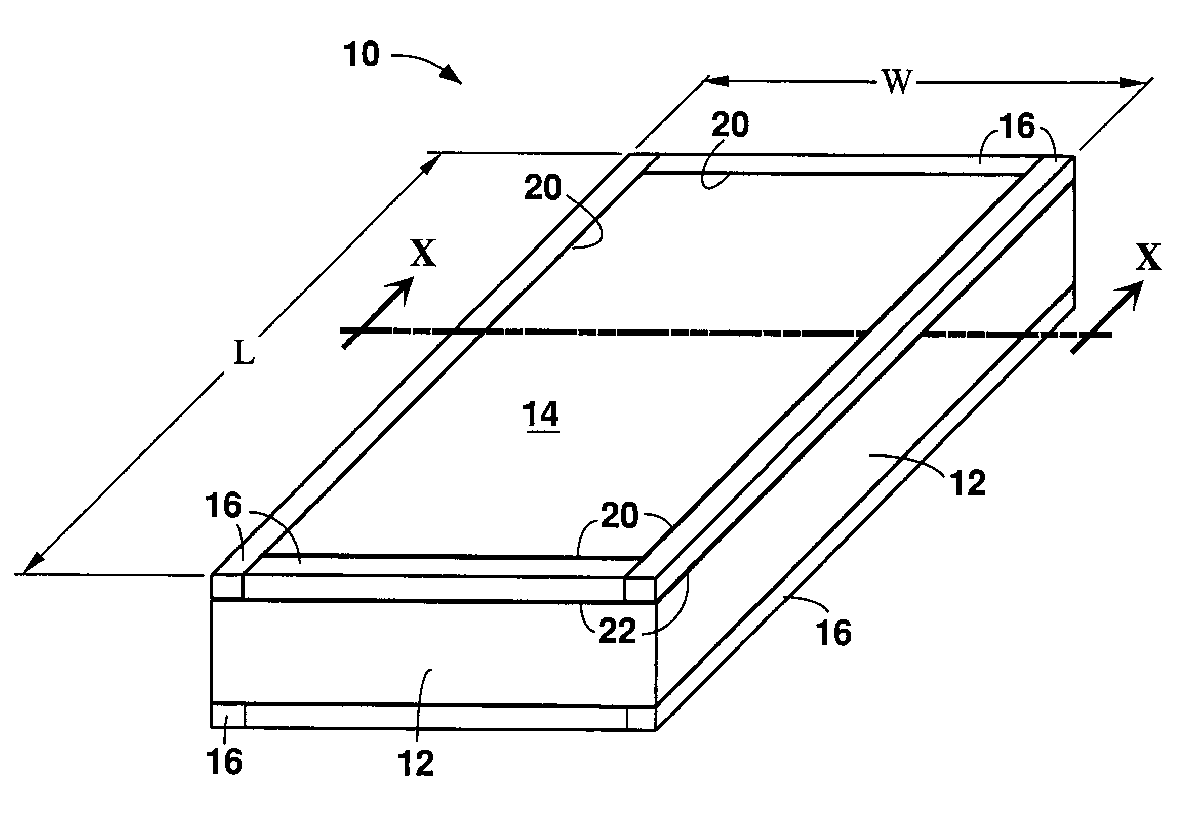
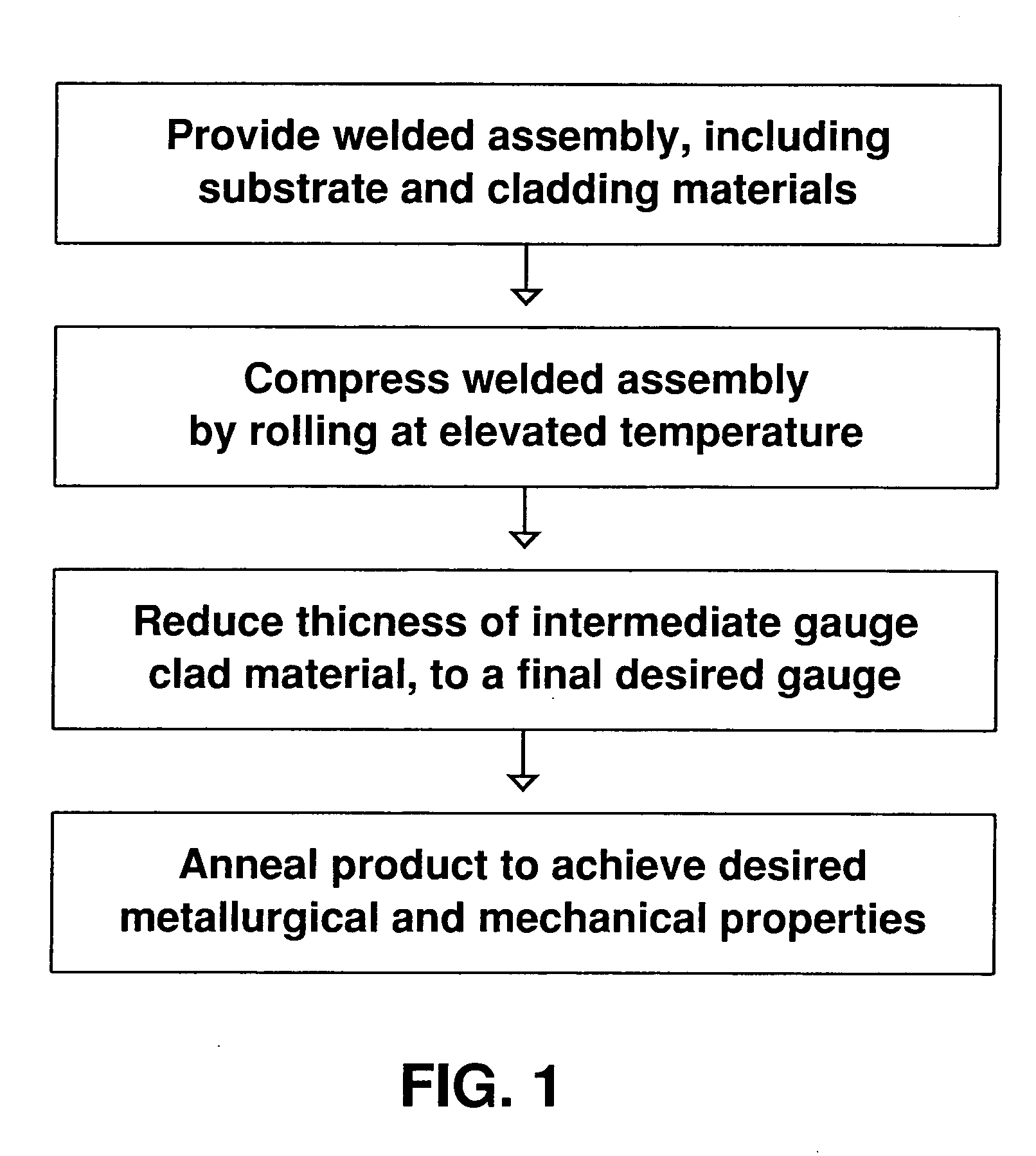
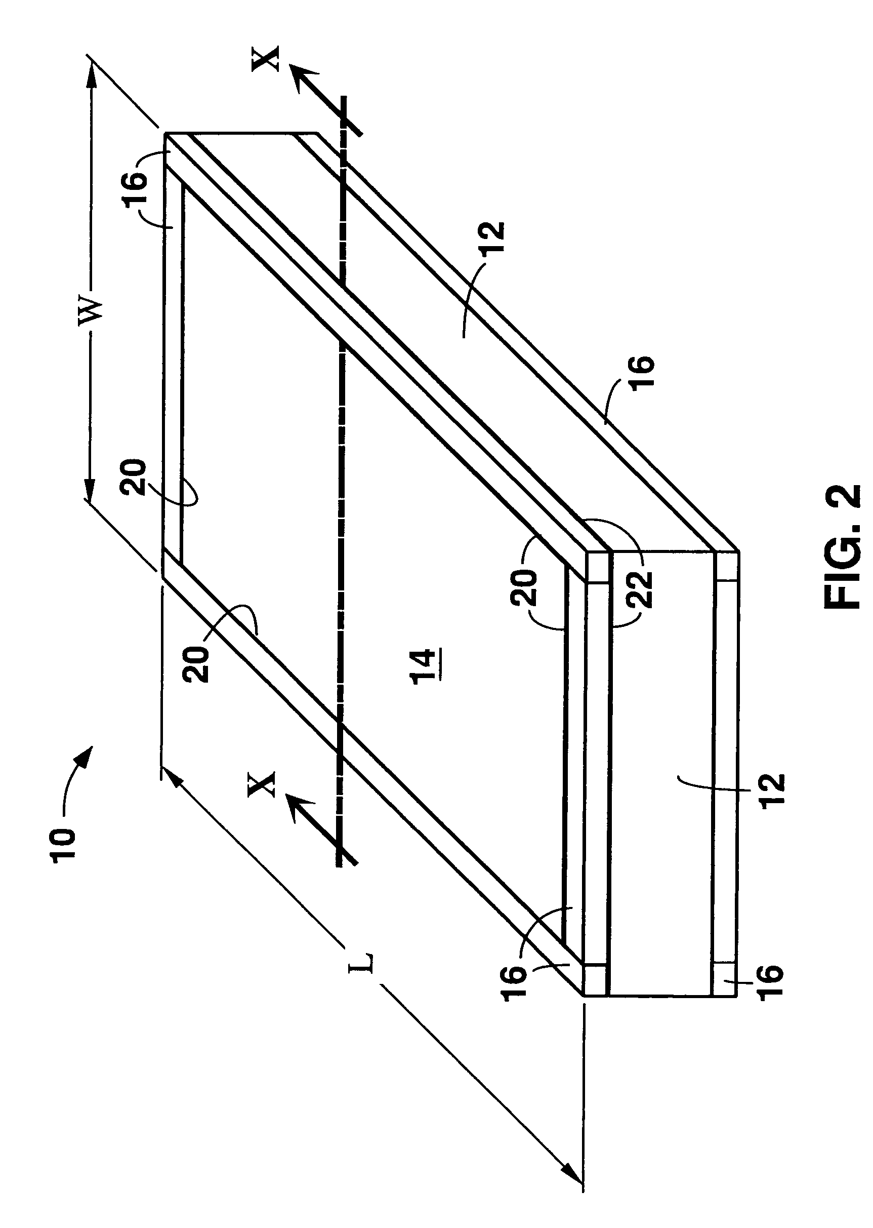
[0069] A welded assembly was prepared to produce a nickel double-clad stainless steel. The assembly comprised a 2 to 2½ inch thick T-316L stainless steel plate sandwiched between two ½ to ¾ inch thick nickel (UNS 02201) plates. The length and width dimensions of the nickel cover plates were smaller than the stainless steel core plate, and the nickel plates were centered on the faces of the stainless steel core plate. In this way, a margin was left around the perimeter of each face of the core plate that was not covered by the cover plate disposed on the face. A frame constructed of ½× 1 / 2 inch thick T-304 stainless steel bar stock was positioned in the margin on each face of the core plate, around the periphery of each of the cover plates. The stainless steel frame was intended to “dam” the lower hot strength (and therefore more fluid) nickel during hot rolling and to inhibit or prevent the nickel material from flowing beyond the edges of the core plate material as the entire asse...

example 2

[0078] A welded assembly constructed substantially the same as in Example 1 was prepared. As in the assembly of Example 1, a 1 / 2 inch gap was left between each of the nickel cover plate edges and the edges of the stainless steel framing material. In order to provide extra support against any lateral movement of the cover plates during rolling, but to still allow space for the cladding material to flow, two short end dams were designed into the framing elements such that each included two ½ inch tabs that mate flush against the adjacent cover plate. This arrangement is shown in FIG. 13, which shows one surface of the assembly 310 in which nickel plate 312 and T-304 stainless steel framing elements 314, 316 are positioned on T-316L stainless steel plate 318. Opposed framing elements 314 include tabs 320 flush with the adjacent cover plate 312. The nickel cover plates and framing elements 314, 316 were then welded in place on the stainless steel core plate 318 in a manner similar to ...

example 3

[0081] Observation of the assemblies of Examples 1 and 2 above indicated that the nickel cover plate material did not flow over the stainless steel framing and was fully contained within the framing during hot rolling reduction. Thus, the % inch gap between cover plates and the framing elements was eliminated in the assembly of this Example 3. It is believed that such design may provide a higher yield of double-clad material since without the gaps the cover plate can cover a larger percentage of the surface width of the core plate. FIG. 15 shows the welded assembly 410 of Example 3 with the cover plate 412 welded to the butted-up framing elements 416 and the framing elements 416 welded to the core plate 414. As shown in FIG. 15, hydraulic tubing 420 was welded to an evacuation bore in the side of the 2-inch thick core plate 414. The evacuation bore passed into the core plate 414 and intersected at a right angle with a bore drilled entirely through the core plate 414, opening at the ...


PUM

PropertyMeasurementUnit
Lengthaaaaaaaaaa
Widthaaaaaaaaaa
Strengthaaaaaaaaaa

Abstract

A method for producing a single-clad or multiple-clad product includes providing a welded assembly comprising a cladding material disposed on a substrate material. Both the substrate material and the cladding material are individually selected alloys. At least a first edge of the cladding material of the welded assembly does not extend to a first edge of the substrate material and thereby provides a margin between the first edges. A material that is an alloy having hot strength greater than the cladding material is within the margin and adjacent the first edge of the cladding material. The welded assembly is hot rolled to provide a hot rolled band, and the material within the margin inhibits the cladding material from spreading beyond the edge of the substrate material during the hot rolling. In certain embodiments of the methods, the substrate material is stainless steel and the cladding material is nickel or a nickel alloy.

Description

BACKGROUND OF THE TECHNOLOGY [0001] 1. Field of Technology [0002] The present disclosure relates to clad alloy substrates and to methods of making such clad materials. The present disclosure also relates to articles of manufacture made from or including clad alloy substrates and to methods of making such articles of manufacture. [0003] 2. Description of the Background of the Technology [0004] In certain applications requiring a material combining high strength with corrosion resistance, clad alloys are used. One common example of a clad alloy exhibiting favorable strength and corrosion resistance includes a stainless steel layer clad on its opposed surfaces with a layer of nickel or a nickel-base alloy (i.e., an alloy that is predominantly composed of nickel). Applications in which such clad materials are used include chemical cisterns, chimney flues, batteries, tubing, heat exchangers, piping for oil and gas, tanks for chemicals, and cookware. The stainless steel layer provides rel...

Claims


Application Information

Patent Timeline
IPC IPC(8): B21D39/00B23K20/04B23K33/00B23P11/00
CPCB23K20/04B23K2103/172B23K33/00B23P11/00Y10S29/904Y10T29/49936Y10T29/49366Y10T428/12264Y10T428/12937Y10T428/12944Y10T29/49924Y10T428/12951Y10T428/12507Y10T428/12486Y10T428/12493Y10T29/49908B23K2103/16B23K20/227
Inventor BERGSTROM, DAVID S.SCHOTT, KRIS J.TARHAY, MARK A.
Owner ATI PROPERTIES
Why Eureka
Try Eureka