Control device of internal combustion engine

a control device and internal combustion engine technology, applied in the direction of electric control, combustion-air/fuel-air treatment, machines/engines, etc., can solve the problems of internal combustion engines of the fuel injection type disclosed in these publications that cannot overcome the fluctuation of air-fuel ratios, impair combustion, etc., to suppress the deterioration of emissions and reduce the performance.

Active Publication Date: 2005-12-15
TOYOTA JIDOSHA KK
View PDF11 Cites 98 Cited by
  • Summary
  • Abstract
  • Description
  • Claims
  • Application Information

AI Technical Summary

Benefits of technology

[0015] The invention has been made for overcoming the above problems, and it is an object of the invention to provide a control device of an internal combustion engine, in which fuel injection is shared by a first fuel injection unit injecting fuel into a cylinder and a second fuel

Problems solved by technology

This may cause fluctuations in air-fuel ratio to fluctuate and impair the combustion.
However, Japanese Patent Laying-Open Nos. 2001-020837 and 05-231221 have not disclosed correction of the fuel injection amount during execution of the purge processing.
Therefore, the internal combustion engines of the fuel injection type disclosed in these publications cannot overcome the problems (e.g., lowering of performance due to adhesion of deposits and emission deterioration due to fluctuations in air-fuel ratio) during execution of

Method used


Image

  • Control device of internal combustion engine
  • Control device of internal combustion engine
  • Control device of internal combustion engine

Examples


first embodiment

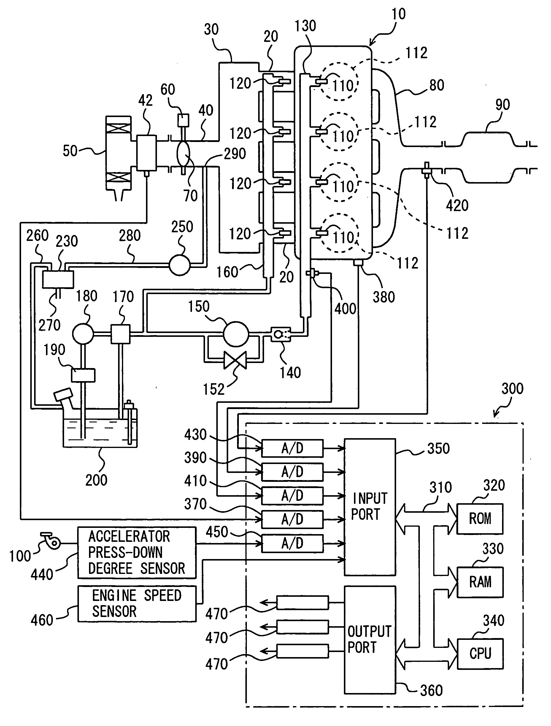
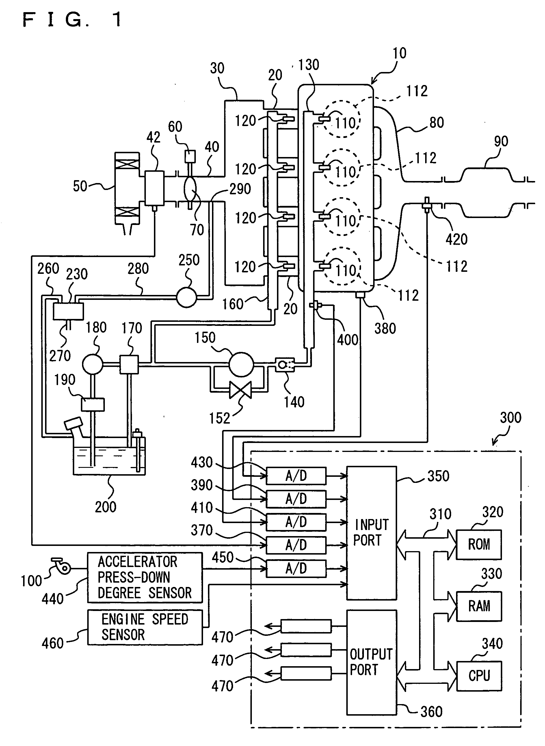
[0105]FIG. 1 shows a schematic structure of an engine system controlled by an engine ECU (Electronic Control Unit), which is a control device of an internal combustion engine according to a first embodiment of the invention. Although FIG. 1 shows an inline four-cylinder gasoline engine, the invention is not restricted to such an engine.

[0106] As shown in FIG. 1, an engine 10 includes four cylinders 112, which are each connected to a common surge tank 30 via a corresponding intake manifold 20. Surge tank 30 is connected to an air cleaner 50 via an intake duct 40. An air flow meter 42 as well as a throttle valve 70 driven by an electric motor 60 are arranged in intake duct 40. The degree of opening of throttle valve 70 is controlled according to an output signal of an engine ECU 300 independently of an accelerator 100. Each cylinder 112 is coupled to a common exhaust manifold 80, which is coupled to a three-way catalytic converter 90.

[0107] For each cylinder 112, the engine is provi...

second embodiment

[0153] A control device of an internal combustion engine according to a second embodiment of the invention will now be described. The second embodiment employs the same structures and operations as those in FIGS. 1 to 3 of the first embodiment, and therefore description thereof is not repeated.

[0154] Referring to FIG. 10, description will now be given on a control structure of a program for correcting the purged fuel amount when the purge control is being executed. The control program illustrated in FIG. 10 is executed at every predetermined time or every predetermined crank angle.

[0155] In step S2400, engine ECU 300 determines whether the purge control execution flag is on or not. When the purge control execution flag is on (YES in S2400), the process proceeds to step S2410. If not (NO in S2400), the processing ends.

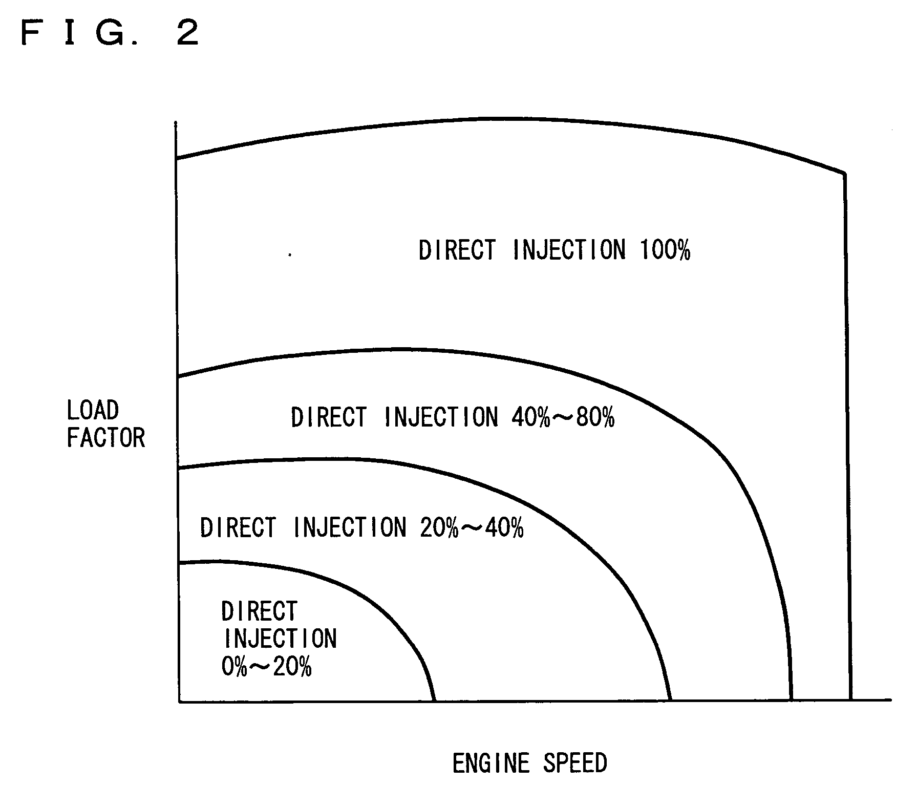
[0156] In step S2410, engine ECU 300 calculates an injection sharing ratio (DI ratio) r. The map of FIG. 2 is used for calculating injection sharing ratio (DI ratio)...

third embodiment

[0175] Description will now be given on a control device of an internal combustion engine according to a third embodiment of the invention. The third embodiment employs the same structures and operations as those in FIGS. 1 to 3 of the first embodiment, and therefore description thereof is not repeated.

[0176] Referring to FIG. 13, description will now be given on a control structure of a program for correcting the purged fuel amount when the purge control is being executed. The control program illustrated in FIG. 13 is executed at every predetermined time or every predetermined crank angle.

[0177] In step S3100, engine ECU 300 determines whether the purge control execution flag is on or not. When the purge control execution flag is on (YES in S3100), the process proceeds to step S3110. If not (NO in S3100), the processing ends.

[0178] In step S3110, engine ECU 300 calculates injection sharing ratio r. The map of FIG. 2 is used for this calculation. In step S3120, engine ECU 300 cal...


PUM


Abstract

When an injection sharing ratio r is neither 0 nor 1, an engine ECU executes a program including a step of calculating a purge reduction amount of an in-cylinder injector as fpg×r and calculating a purge reduction amount of an intake manifold injector as fpg×(1-r) when performing purge processing according to a current fuel injection sharing ratio of the injectors, and a step of calculating a correction fuel injection amount of the in-cylinder injector by raising the fuel injection amount to a minimum fuel injection amount, and calculating a correction fuel injection amount of the intake manifold injector by subtracting the raised amount from the fuel injection amount of the intake manifold injector when the fuel injection amount of the in-cylinder injector calculated by using the purge reduction amount is lower than the minimum injection amount.

Description

[0001] This nonprovisional application is based on Japanese Patent Applications Nos. 2004-177416, 2004-214443, 2004-214498, 2004-273765, 2004-273782, 2004-320973, and 2005-078358 filed with the Japan Patent Office on Jun. 15, 2004, Jul. 22, 2004, Jul. 22, 2004, Sep. 21, 2004, Sep. 21, 2004, Nov. 4, 2004, and Mar. 18, 2005, respectively, the entire contents of which are hereby incorporated by reference. BACKGROUND OF THE INVENTION [0002] 1. Field of the Invention [0003] The present invention relates to a control device of an internal combustion engine including a first fuel injection unit (an injector for in-cylinder injection) injecting fuel into a cylinder and a second fuel injection unit (an injector for intake manifold injection) for injecting the fuel into an intake manifold or an intake port, and particularly to a control device for executing purge processing of vaporized fuel gas. [0004] 2. Description of the Background Art [0005] A certain kind of known internal combustion en...

Claims


Application Information

Patent Timeline
IPC IPC(8): F02D41/00F02D41/30F02M69/04
CPCF02D41/0042F02D41/3023F02D41/3094F02M63/029F02M69/046
Inventor OKUBO, SHIGEOMASHIKI, ZENICHIROSHIBAGAKI, NOBUYUKINOMURA, HIROYUKISHOGENJI, YOSHIYUKIKINOSE, KENICHIMATSUBARA, TAKUJINAKAYAMA, YUSUKESONODA, YUKIHIROMORITA, KOJI
Owner TOYOTA JIDOSHA KK
Why Eureka
Try Eureka