
Continuous phase modulation system and method with added orthogonal signals

a phase modulation and orthogonal signal technology, applied in the field of communication systems, can solve the problems of not greatly increasing the complexity of the receiver, and achieve the effects of increasing the bandwidth of the signal, improving the bit error rate performance, and increasing the number of bits

Inactive Publication Date: 2005-12-15
HARRIS CORP
View PDF10 Cites 19 Cited by
  • Summary
  • Abstract
  • Description
  • Claims
  • Application Information

AI Technical Summary

Benefits of technology

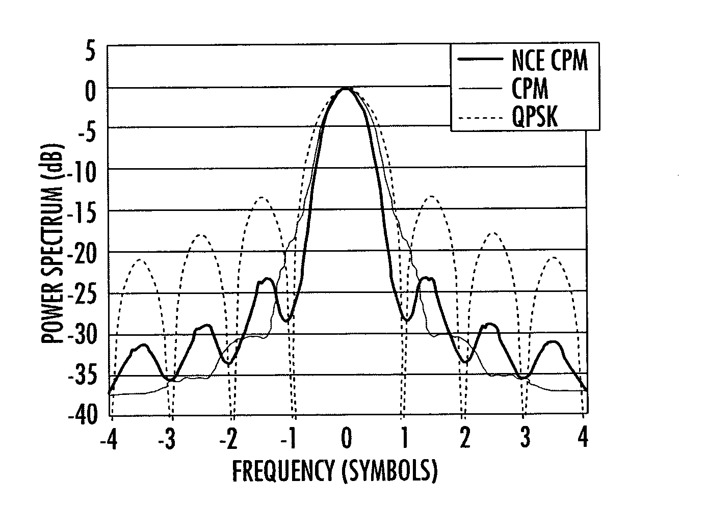
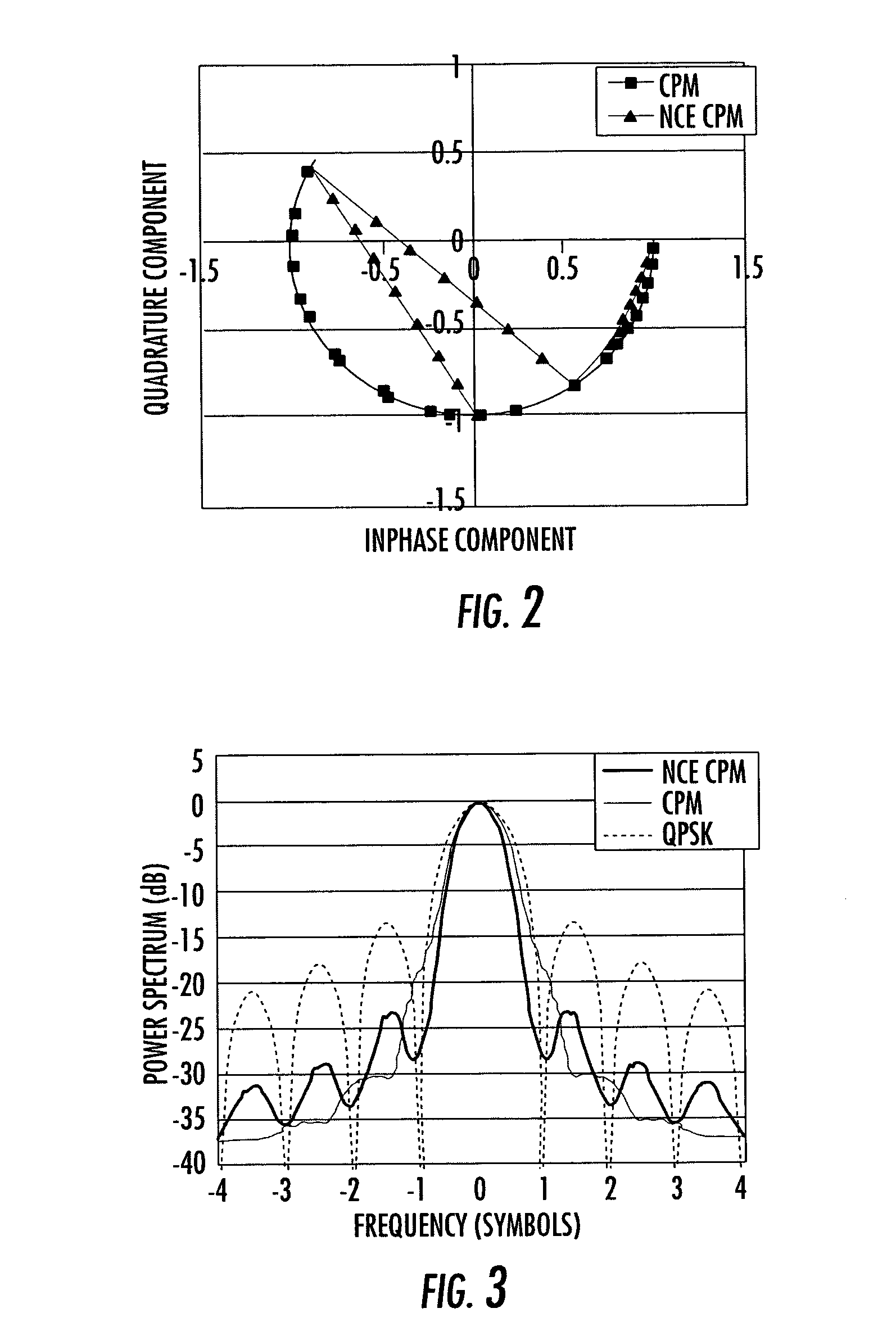
[0006] The present invention is applicable to communication systems and products in general and particularly systems that require modulation schemes that occupy a fixed bandwidth channel (LOS, cable or SATCOM) (fixed frequency spectrum). This invention takes advantage of the memory (usually represented as a trellis structure) of a coded waveform (i.e., TCM M-PSK, TCM M-ASK, continuous FSK, TCM M-QAM, or CPM with a convolutional (or other type) FEC code) with a novel technique to increase the bandwidth of the signal and either improve the bit error rate performance or increase the number of bits which can be encoded into a single symbol.
[0007] The addition of orthogonal or pseudo-orthogonal modulated waveforms (i.e., sin (ft / T), sin (2ft / T), PN spread sequences, etc.) increases the distance property of uncoded, transmitted bits while taking advantage of the underlying memory (coding) scheme of those bits / symbols which are most likely to be received in error. The amplitude modulated waveforms would provide discrimination to differentiate between different amplitude signals. In this approach, the orthogonal or pseudo-orthogonal signals are added to the signal space of a modulation type to create a new, hybrid signal. The demodulation of this hybrid signal requires some modification to the receiver for optimal performance but does not effect the complexity of the original trellis decoder. Thus, the receiver complexity is not greatly increased. The addition of one orthogonal (or pseudo-orthogonal) waveform to a CPM-encoded signal is advantageous. This hybrid approach can be used with any modulation type which takes advantage of modulation or channel memory.
[0008] In accordance with the present invention, a system and method forms an encoded signal and uses a signal generator for generating a coded waveform having a trellis structure. A modulator is operative with the signal generator and adds at least one orthogonal or pseudo-orthogonal waveform to a trellis structure of the coded waveform to create a non-constant envelope modulated signal that has increased bandwidth, improved bit error rate, or an increased number of bits encoded into a single symbol. The modulator is operative for amplitude shaping the coded waveform with integer or non-integer frequency multiples of amplitude modulated signals. A demodulator employs a Fast Fourier Transform (FFT) and branch metrics and discriminates between amplitude modulated signals. It is also operative for increasing the number of cycles per symbol for a pair of amplitude modulated signals, increasing higher order modulation within the encoded waveform by increasing orthogonal symbols, and generating a symbol alphabet using a sum of orthogonal frequencies.
[0009] In an example of the present invention, the modulator is operative for creating a multiple-ary encoded waveform using multiple-ary symbols and at least one extra-encoded amplitude modulated bit. The multiple-ary encoded waveform could include a Sin (Fs / 2) or Sin (Fs) amplitude shape. It is also operative for changing a phase offset per symbol to provide sufficient distance for a parallel path to work with a trellis structure and increasing the distance between constellation points in the trellis. Higher orthogonal signals can be created using a sum of orthogonal signals (Sin (Fs)+Sin (2Fs).

Problems solved by technology

Thus, the receiver complexity is not greatly increased.

Method used


Image

  • Continuous phase modulation system and method with added orthogonal signals
  • Continuous phase modulation system and method with added orthogonal signals
  • Continuous phase modulation system and method with added orthogonal signals

Examples


Embodiment Construction

[0028] The present invention will now be described more fully hereinafter with reference to the accompanying drawings, in which preferred embodiments of the invention are shown. This invention may, however, be embodied in many different forms and should not be construed as limited to the embodiments set forth herein. Rather, these embodiments are provided so that this disclosure will be thorough and complete, and will fully convey the scope of the invention to those skilled in the art. Like numbers refer to like elements throughout, and prime notation is used to indicate similar elements in alternative embodiments.

[0029] The present invention is applicable to communication systems and products in general and particularly systems that require modulation schemes that occupy a fixed bandwidth channel (LOS, cable or SATCOM) (fixed frequency spectrum). The present invention can take advantage of the memory (usually represented as a trellis structure) of a coded waveform (i.e., PSK, ASK,...


PUM


Abstract

A system and method of the present invention forms a hybrid encoded signal. A signal generator generates a coded waveform having a trellis structure, such as a continuous phase modulated signal. A modulator is operative with the signal generator and adds at least one orthogonal or amplitude modulated waveform to a trellis structure of the coded waveform to create a non-constant envelope modulated signal that has at least one of increased bandwidth, improved bit error rate, or an increased number of bits encoded into a single symbol.

Description

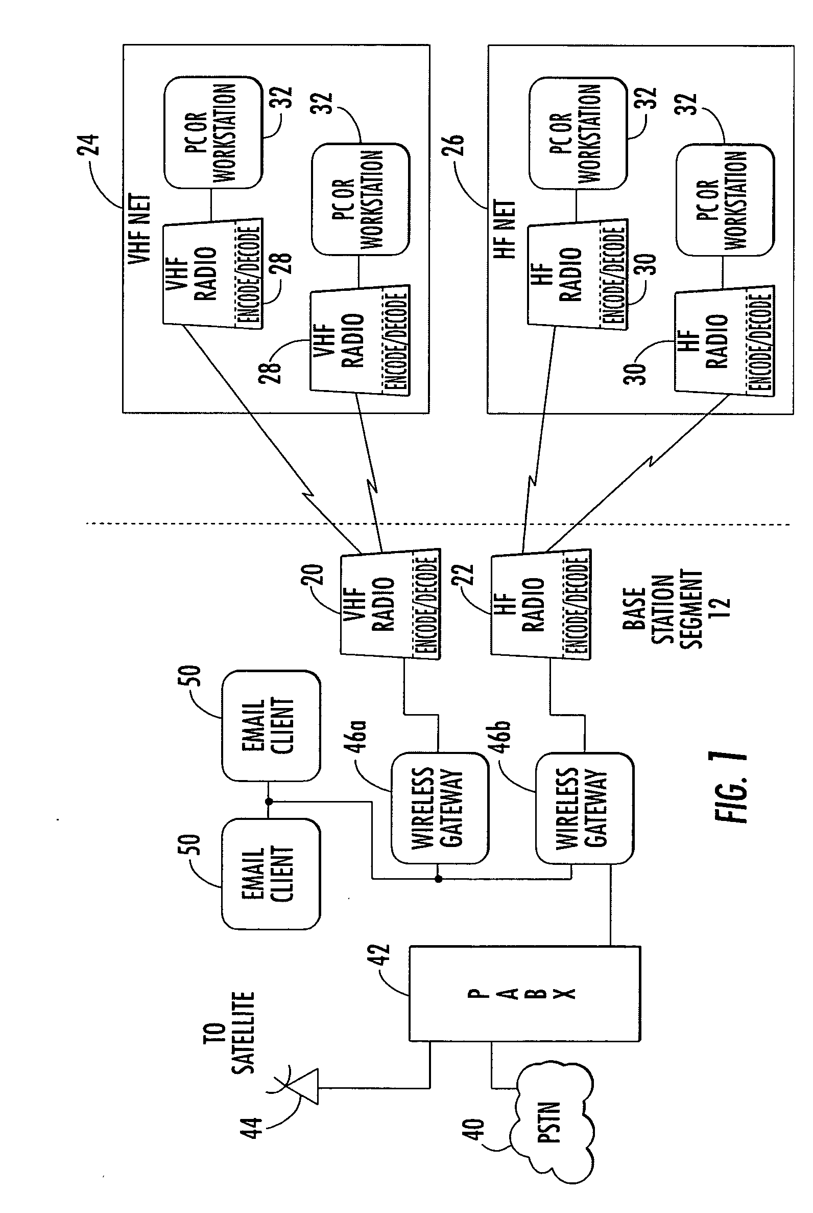
FIELD OF THE INVENTION [0001] The present invention relates to the field of communications systems, and more particularly, the present invention relates to communications systems and related methods that use continuous phase modulation and similar modulation schemes. BACKGROUND OF THE INVENTION [0002] Some multi-band or other tactical radios operate in the high frequency (HF), very high frequency (VHF) (for satellite communications), and ultra high frequency (UHF) bands. The range of multi-band tactical radios can operate over about 2 through about 512 MHz frequency range. Next generation radios should cover about 2.0 to about 2,000 MHz to accommodate high data rate waveforms and less crowded frequency bands. This high frequency transmit mode is governed by standards such as MIL-STD-188-141B. UHF standards, on the other hand, provide different challenges over the 225 to about 512 MHz frequency range, including short-haul line-of-sight (LOS) communication and satellite communications...

Claims


Application Information

Patent Timeline
IPC IPC(8): H04L5/12H04L27/20
CPCH04L27/201
Inventor NORRIS, JAMES A.NIETO, JOHN W.
Owner HARRIS CORP
Learn More