Magnetoresistive spin-valve sensor and magnetic storage apparatus
- Summary
- Abstract
- Description
- Claims
- Application Information
AI Technical Summary
Benefits of technology
Problems solved by technology
Method used
Image
Examples
first embodiment
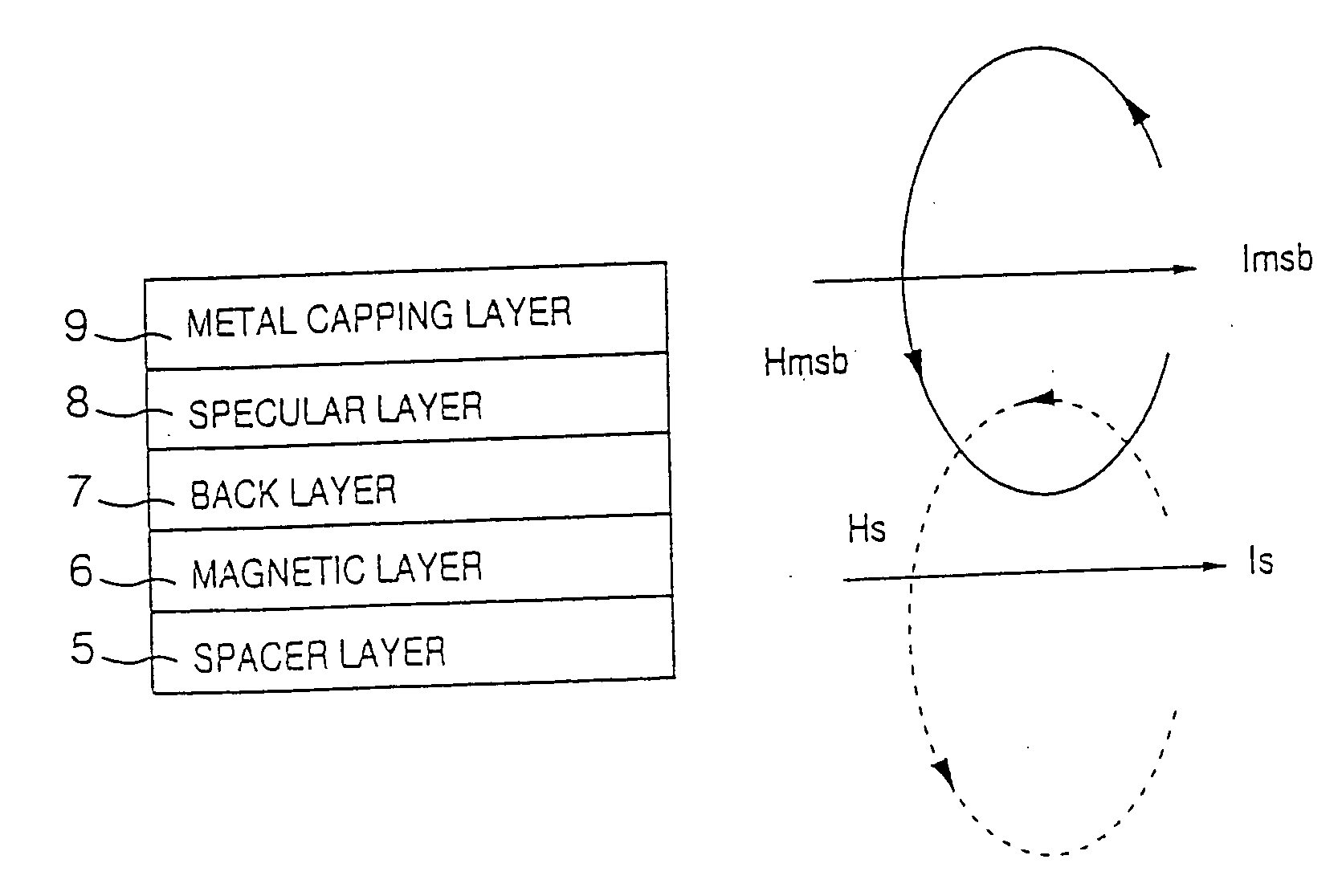
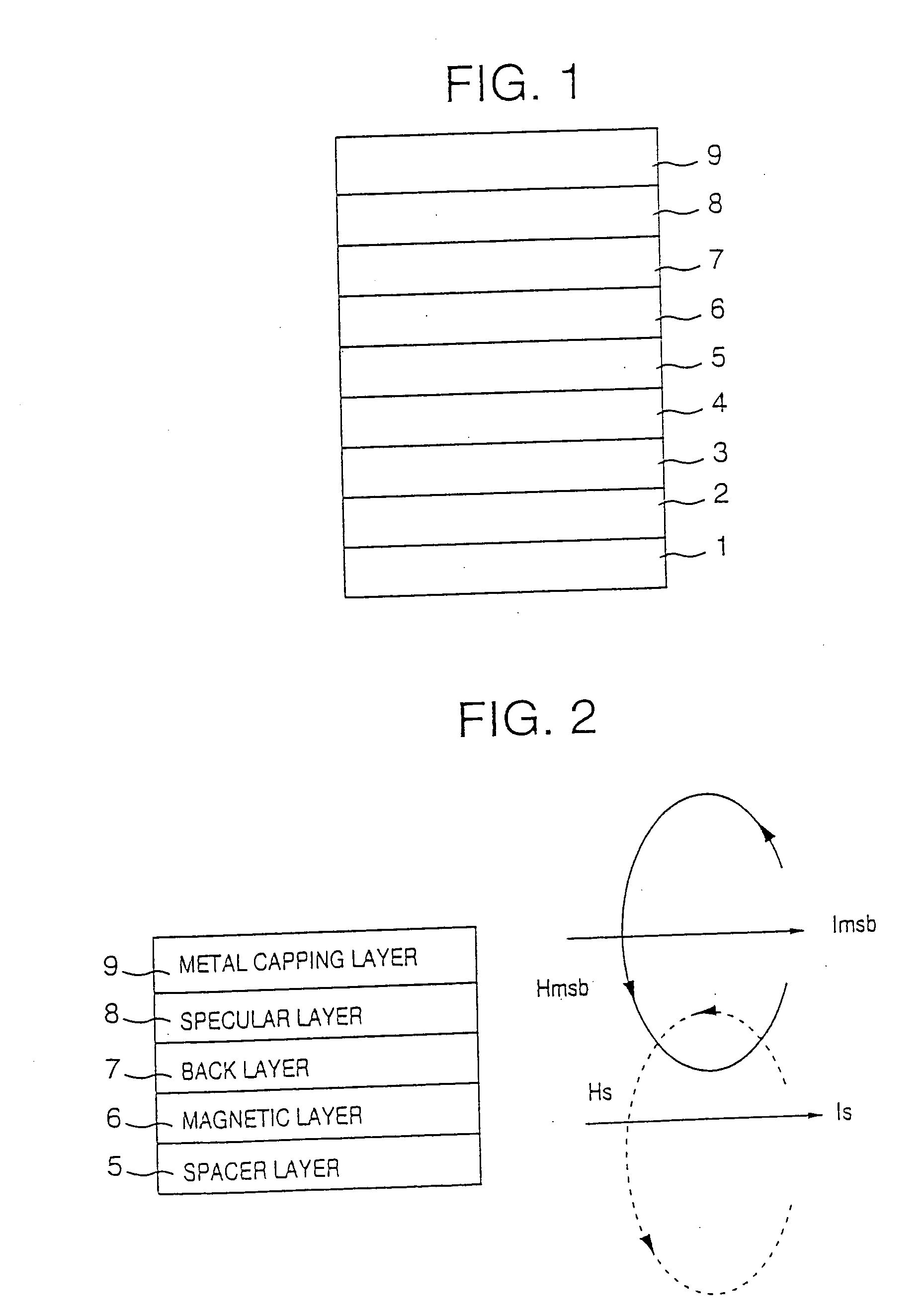
[0022]FIG. 1 is a cross sectional view showing the general structure of an important part of a magnetoresistive spin-valve sensor according to the present invention. The magnetoresistive spin-valve sensor shown in FIG. 1 generally includes a substrate 1, an underlayer 2, an antiferromagnetic layer 3, a first magnetic layer 4, a spacer layer 5, a second magnetic layer 6, a back layer 7, a specular layer 8, and a metal capping layer 9.
[0023] The first magnetic layer 4 is made of a magnetic material such as a Co-based alloy, and may have a single-layer structure or a multi-layer structure. The first magnetic layer 4 forms a pinned layer of the magnetoresistive spin-valve sensor. The spacer layer 5 is made of a nonmagnetic metal such as Cu. The second magnetic layer 6 is made of a soft magnetic material such as a Co-based alloy, and forms a free layer of the magnetoresistive spin-valve sensor. The second magnetic layer 6 may have a single-layer structure or a multi-layer structure. The ...
second embodiment
[0037]FIG. 7 is a cross sectional view showing the general structure of an important part of the magnetoresistive spin-valve sensor according to the present invention. In FIG. 7, those parts which are the same as those corresponding parts in FIG. 1 are designated by the same reference numerals, and a description thereof will be omitted.
[0038] In the first embodiment described above, the structure shown in FIG. 1 is provided at a top portion of the magnetoresistive spin-valve sensor. On the other hand, in this second embodiment, the structure shown in FIG. 7 is embedded inside the magnetoresistive spin-valve sensor. In this second embodiment, the magnetoresistive spin-valve sensor has an inverted structure as compared to that of the first embodiment, and the layers are disposed in a reverse order to that of the first embodiment.
third embodiment
[0039]FIG. 8 is a cross sectional view showing the general structure of an important part of the magnetoresistive spin-valve sensor according to the present invention. In FIG. 8, those parts which are the same as those corresponding parts in FIG. 1 are designated by the same reference numerals, and a description thereof will be omitted.
[0040] In the first embodiment described above, the structure shown in FIG. 1 is provided at a top portion of the magnetoresistive spin-valve sensor. On the other hand, in this third embodiment, the structure shown in FIG. 7 is embedded inside the magnetoresistive spin-valve sensor. In this third embodiment, the magnetoresistive spin-valve sensor has an inverted structure as compared to that of the first embodiment, and the layers are disposed in a reverse order to that of the first embodiment.
[0041] Furthermore, in this third embodiment, a metal underlayer 9-1 is provided under the specular layer 8. The metal underlayer 9-1 can provide the rest of t...
PUM
 Abstract
Description
Claims
Application Information
 - R&D
- Intellectual Property
- Life Sciences
- Materials
- Tech Scout
- Unparalleled Data Quality
- Higher Quality Content
- 60% Fewer Hallucinations
Browse by: Latest US Patents, China's latest patents, Technical Efficacy Thesaurus, Application Domain, Technology Topic, Popular Technical Reports.
© 2025 PatSnap. All rights reserved.Legal|Privacy policy|Modern Slavery Act Transparency Statement|Sitemap|About US| Contact US: help@patsnap.com


