Switching power supply circuit

a power supply circuit and power supply technology, applied in the direction of electric variable regulation, process and machine control, instruments, etc., can solve the problems of substantially impossible control of switching frequency, difficult to obtain a practical numerical value as power conversion efficiency, and degrade the power factor indicating the efficiency of use of power supply, etc., to achieve the range (necessary control range) of switching frequency, which is necessary for stabilization, and reduce the effect of the rang

Inactive Publication Date: 2005-12-22
SONY CORP
View PDF5 Cites 44 Cited by
  • Summary
  • Abstract
  • Description
  • Claims
  • Application Information

AI Technical Summary

Benefits of technology

[0090] By thus setting a value for loose coupling as the composite coupling coefficient of the converter transformer, it is possible to obtain a steep unimodal output characteristic in response to the frequency signal of the switching frequency (switching output) as input to the coupling type resonant circuit. As a result, the range (necessary control range) of the switching frequency, which range is necessary for stabilization, can be reduced as compared with a case in which a series resonant circuit is formed on only the primary side.

Problems solved by technology

Generally, when a commercial power supply voltage is rectified, a current flowing in a smoothing circuit has a distorted waveform, thus causing a problem in that a power factor indicating the efficiency of use of the power supply is degraded.
With a maximum variable range of the above-mentioned oscillation and drive IC, it is substantially impossible to control the switching frequency.
Even if the oscillation and drive IC can realize such a wide frequency control range, a high switching frequency of 400 kHz or 500 kHz involves an increase in losses at the switching device and the transformer, for example, thus making it very difficult to obtain a practical numerical value as the power conversion efficiency.
For these reasons, it is substantially impossible for resonant converters to be configured to deal with the wide range by switching frequency control.
However, the power supply circuit shown in FIG. 36 has the following problems.
In addition, since the active filter circuit performs a hard switching operation, a very high level of noise occurs.
Therefore, a relatively serious measure to suppress noise is required.
Thus, the actual circuit requires measures against noise using a very large number of parts, which results in an increase in cost and an increase in the mounting area of the power supply circuit board.
Since switching timings of the switching device Q11 and the current resonant converter are thus independent of each other, primary side ground potentials obtained by switching operations of the switching device Q11 and the current resonant converter interfere with each other and thus become unstable, so that an abnormal oscillation, for example, tends to occur.
This, for example, makes circuit design difficult and degrades reliability.

Method used


Image

  • Switching power supply circuit
  • Switching power supply circuit
  • Switching power supply circuit

Examples


Embodiment Construction

[0131] The best mode for carrying out the invention (hereinafter referred to as embodiments) will hereinafter be described. In the description below of the embodiments, the embodiments are roughly classified into four embodiments, that is, a first, a second, a third, and a fourth embodiment. Further, variations in the categories of the first, second, third, and fourth embodiments will be represented by embodiments 1-1 to 1-n, 2-1 to 2-n, 3-1 to 3-n, and 4-1 to 4-n according to the numbers (n) of the variations, respectively.

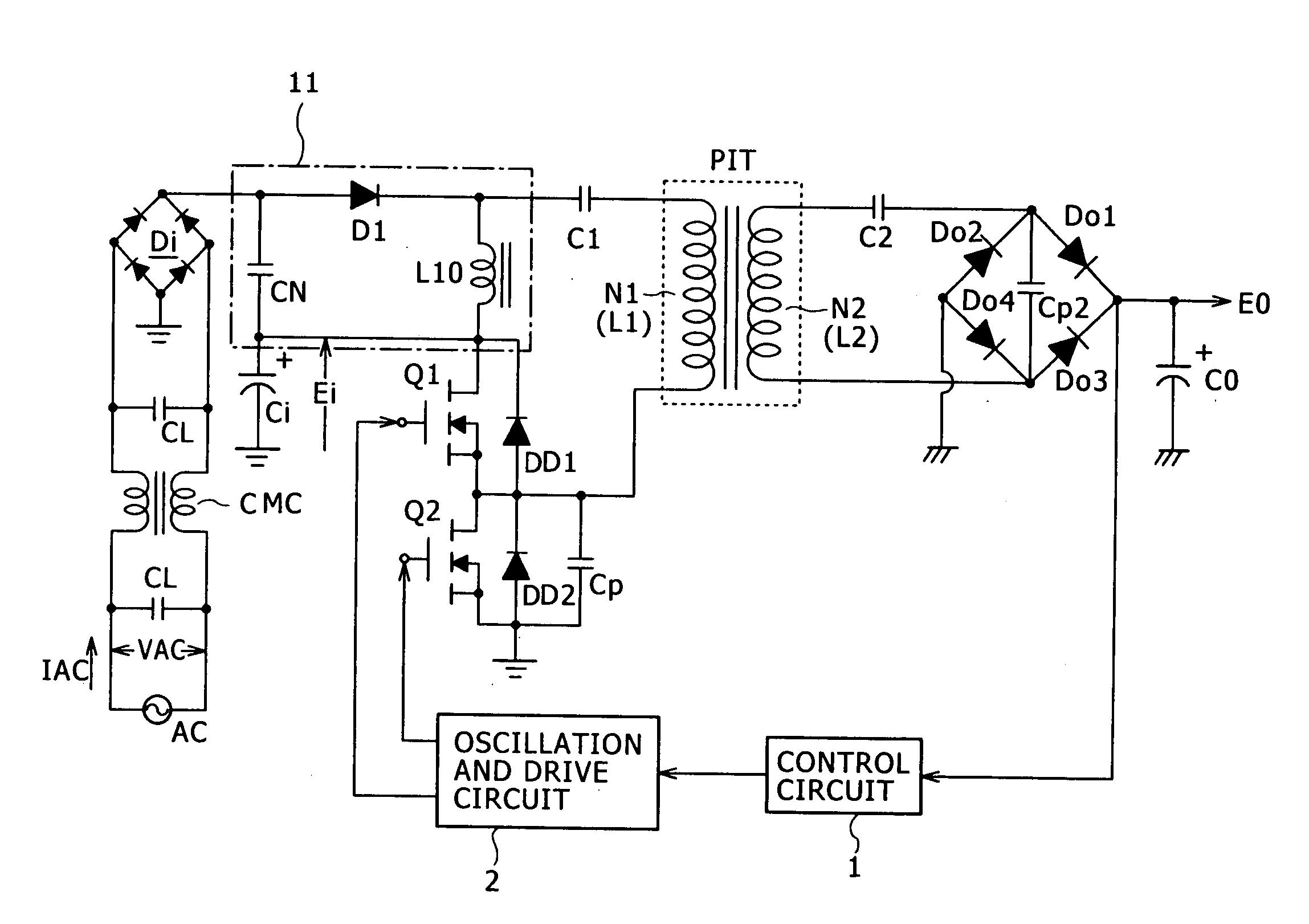
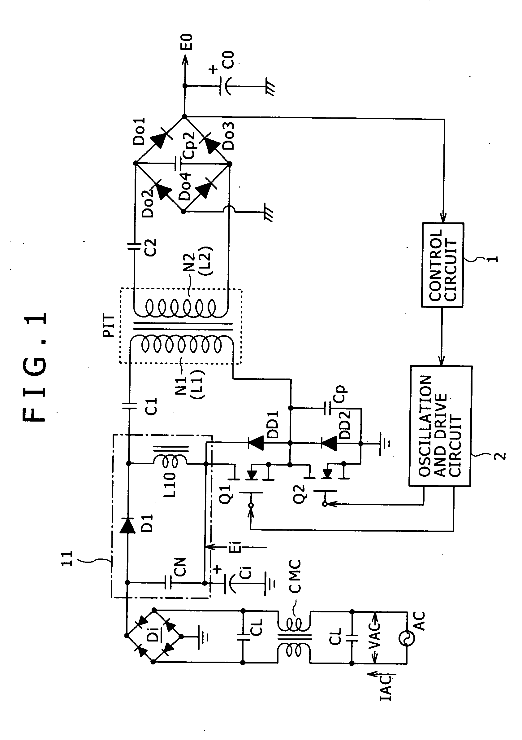
[0132]FIG. 1 is a circuit diagram showing an example of the configuration of a switching power supply circuit according to an embodiment 1-1. The power supply circuit shown in this figure employs a combination of an externally excited current resonant converter of a half-bridge coupling system with a partial voltage resonant circuit as the fundamental configuration on the primary side.

[0133] Also, the power supply circuit shown in this figure employs a so-calle...


PUM


Abstract

A switching power supply circuit includes a primary side series resonant circuit forming a current resonant converter, and a secondary side series resonant circuit formed by at least a secondary winding and a secondary side series resonant capacitor, whereby a coupling type resonant circuit is formed by magnetic coupling of an isolated converter transformer. In order to obtain a unimodal characteristic for this coupling type resonant circuit, the total coupling coefficient of the isolated converter transformer is set to 0.65 or lower. For power factor improvement, a power factor improving circuit of a power regeneration system or a voltage feedback system is provided.

Description

CROSS-REFERENCE TO RELATED APPLICATIONS [0001] The present application claims priority from Japanese Application Nos. 2004-164452 filed Jun. 2, 2004, 2004-194106 filed Jun. 30, 2004, 2004-235912 filed Aug. 13, 2004, 2004-262695 filed Sep. 9, 2004, 2004-265442 filed Sep. 13, 2004 and 2005-082518 filed Mar. 22, 2005, the disclosures of which are hereby incorporated by reference herein. BACKGROUND OF THE INVENTION [0002] The present invention relates to a switching power supply circuit provided as a power supply for various electronic devices. [0003] Recently, due to the development of switching devices capable of withstanding relatively high currents and voltages of high frequency, most power supply circuits that rectify a commercial power supply voltage and obtain a desired direct-current voltage have become switching type power supply circuits. [0004] Switching power supply circuits have a transformer and other devices miniaturized by raising the switching frequency, and are used as...

Claims


Application Information

Patent Timeline
Patent Type & Authority Applications(United States)
IPC IPC(8): H02M1/42H02M3/335H02M3/337
CPCH02M1/4241H02M3/3376Y02B70/1491Y02B70/1433H02M2001/0058Y02B70/126H02M1/0058Y02B70/10H02M3/28
Inventor YASUMURA, MASAYUKI
Owner SONY CORP
Why Eureka
Try Eureka