Boron free joint for superalloy component

a superalloy and joint technology, applied in the field of metalurgical field, can solve the problems of complex fusion welding process, difficult control of superalloy materials, and various types of damage and deterioration of components

Inactive Publication Date: 2005-12-22
SIEMENS ENERGY INC
View PDF47 Cites 6 Cited by
  • Summary
  • Abstract
  • Description
  • Claims
  • Application Information

AI Technical Summary

Problems solved by technology

During the operation of these components in the harsh operating environment of a gas turbine, various types of damage and deterioration of the components may occur.
For example, the surface of a component may become cracked due to thermal cycling or thermo-mechanical fatigue or it may be eroded as a result of impacts with foreign objects and corrosive fluids.
Furthermore, such components may require a materials joining process to close casting core-prints or to repair areas damaged during manufacturing operations even prior to entering service.
Fusion welding of superalloy materials is known to be a difficult process to control due to the tendency of these materials to crack at the area of the weld deposit / joint.
One limitation of brazing is that brazed joints are typically weaker than the base alloy, and so they may not be appropriate in all situations, such as repairs on the most highly stressed areas of the component.
Upon completion of this cycle, typical braze alloys will have formed undesirable large blocky or script-like brittle phases composed of chromium, titanium, and the family of refractory elements (e.g., tungsten, tantalum) combined with the melting point depressants.
These brittle phases weaken the repaired component and decrease its ductility in the region of the repair.
Such a liquid phase diffusion bonding process is capable of forming a joint with material properties approximating but typically not as good as those of the base alloy.

Method used


Image

  • Boron free joint for superalloy component
  • Boron free joint for superalloy component

Examples


Embodiment Construction

[0008] The melting temperatures of various nickel-aluminum alloy compounds are known in the art. It is known that the compounds containing about 60-80 wt. % aluminum (40-20 wt. % nickel) have a melting temperature of about 1,000-800° C. The present inventor has noted the significance of the fact that such melting temperatures are significantly below the melting temperature of a typical nickel-based superalloy, which may be about 1,500° C. The present inventor has innovatively applied such materials in one embodiment of the present invention for joining of nickel-based superalloy components.

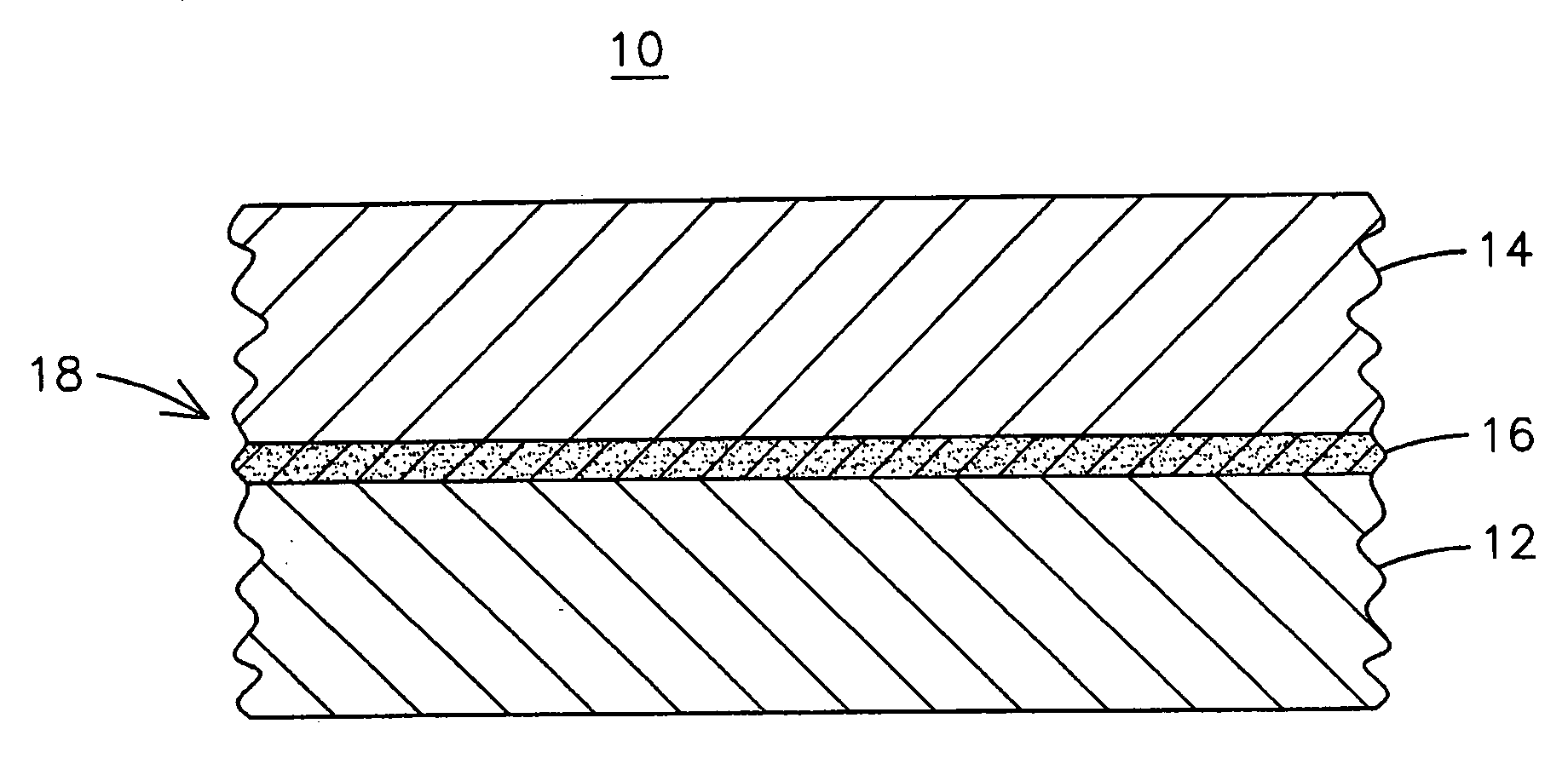
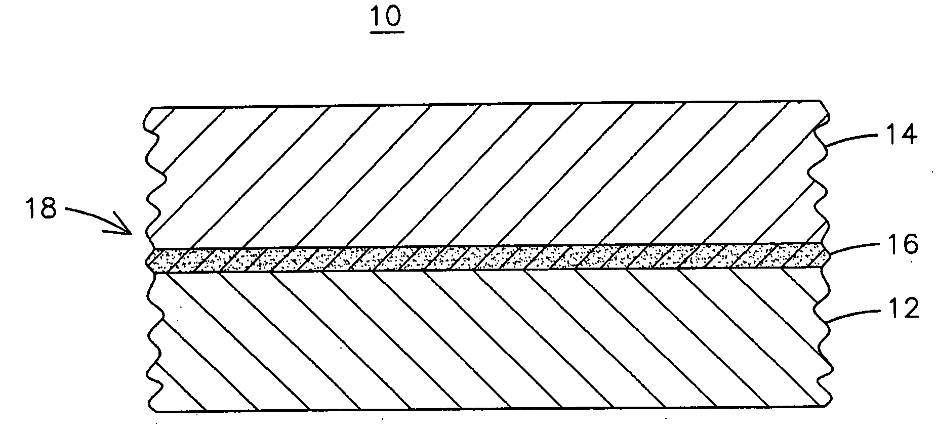
[0009] The FIGURE illustrates a component 10 of a gas turbine engine having a first superalloy substrate material 12 being joined to a second superalloy substrate material 14 by a brazing alloy 16 to form a joint 18. The superalloy substrates 12, 14 may be any nickel-based or cobalt-based superalloy material known in the art. The major elemental constituents in a superalloy material may include n...


PUM

PropertyMeasurementUnit
weight percentaaaaaaaaaa
melting temperatureaaaaaaaaaa

Abstract

A boron-free and silicon-free bonding alloy (16) for joining with a superalloy base material (12, 14). The bonding alloy includes aluminum in a concentration that is higher than the concentration of aluminum in the base material in order to depress the melting temperature for the bonding alloy to facilitate liquid phase diffusion bonding without melting the base material. The concentration of aluminum in the bonding alloy may be at least twice that of the concentration of aluminum in the base material. For joining cobalt-based superalloy materials that do no contain aluminum, the concentration of aluminum in the bonding alloy may be at least 5 wt. %.

Description

FIELD OF THE INVENTION [0001] This application applies generally to the field of metallurgy, and more specifically to the manufacturing and repair of alloy articles, and in particular, to the manufacturing and repair of a superalloy component of a gas turbine engine. BACKGROUND OF THE INVENTION [0002] High temperature nickel-based and cobalt-based superalloys are well known. Examples of such materials include the alloys that are commercially available under the following designations and whose specifications are known in the art: U500; U520; U700; U720; IN 738; IN 718; IN 939; IN 718; MAR-M 002; CM 247; CMSX 4; PWA 1480; PWA 1486; ECY 768 and X45. Superalloy materials are commonly used in the manufacture of gas turbine engine components, including combustors, rotating blades and stationary vanes. During the operation of these components in the harsh operating environment of a gas turbine, various types of damage and deterioration of the components may occur. For example, the surface...

Claims


Application Information

Patent Timeline
Patent Type & Authority Applications(United States)
IPC IPC(8): C22C19/05C22C19/07
CPCC22C19/007C22C19/058C22C19/07Y10T428/12028Y10T428/12931Y10T428/12076Y10T428/12493Y10T428/12771Y10T428/12063
Inventor SRINIVASAN, VASUDEVAN
Owner SIEMENS ENERGY INC
Why Eureka
Try Eureka