Smooth outer coating for combustor components and coating method therefor

a technology of combustor components and outer coatings, which is applied in the direction of solid-state diffusion coatings, superimposed coating processes, natural mineral layered products, etc., can solve the problems of reducing the service life of tbc systems, compromising the thermal protection provided by apstbc, and prolonging the service life of components. , to achieve the effect of reducing the temperature of components and reducing convective and radiant heat transfer

Active Publication Date: 2005-12-22
GENERAL ELECTRIC CO
View PDF6 Cites 32 Cited by
  • Summary
  • Abstract
  • Description
  • Claims
  • Application Information

AI Technical Summary

Benefits of technology

[0008] The present invention generally provides a coating and method for overcoating a TBC on a component used in a high-temperature environment, such as the combustor section of a gas turbine. The invention is particularly directed to a coating that reduces the component temperature by reducing the convective and radiant heat transfer to the component in the combustor section of an industrial gas turbine.

Problems solved by technology

Hot section components of aircraft and industrial (power generation) gas turbine engines are often protected by a thermal barrier coating (TBC), which reduces the temperature of the underlying component substrate and thereby prolongs the service life of the component.
As a result, the thermal protection provided by APSTBC is compromised in environments that have high thermal radiation loads, such as within the combustor section of a gas turbine.
The latter requirement is particularly demanding due to the different coefficients of thermal expansion (CTE) between ceramic materials and the substrates they protect, which are typically superalloys though ceramic matrix composite (CMC) materials are also used.
The service life of a TBC system is typically limited by a spallation event brought on by thermal fatigue.

Method used


Image

  • Smooth outer coating for combustor components and coating method therefor
  • Smooth outer coating for combustor components and coating method therefor
  • Smooth outer coating for combustor components and coating method therefor

Examples


Embodiment Construction

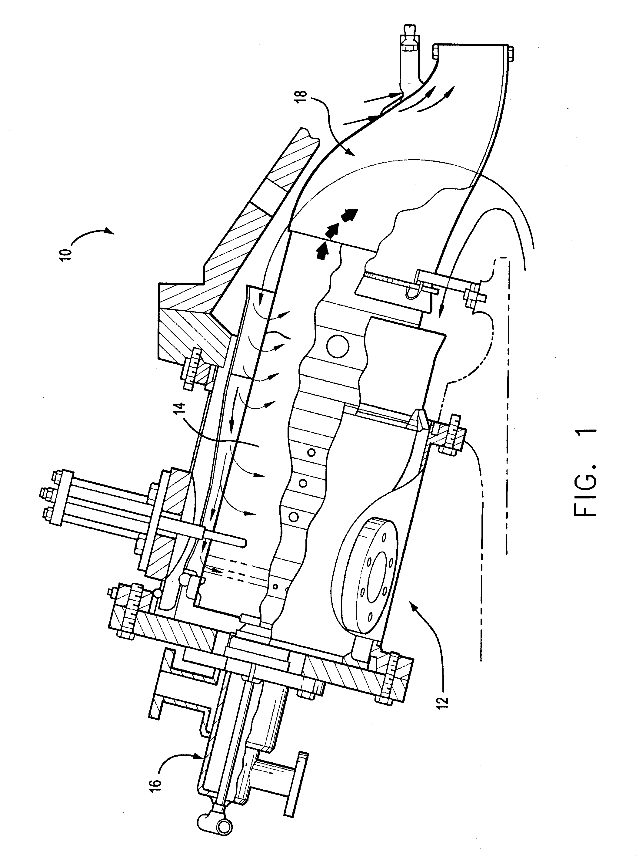
[0016] The present invention will be described in reference to a combustor 12 of an industrial gas turbine 10, a portion of which is shown in cross-section in FIG. 1. The combustor 12 is one of multiple can-annular combustors located about the periphery of the turbine 10, and has a can-type liner 14 whose interior defines a combustion chamber of the turbine 10. The liner 14 is inserted into a transition piece 18 with multiple fuel nozzle assemblies 16 located at the head end of the liner 14. Both fuel and water may be injected into the combustion chamber through the nozzle assemblies 16, with the injection of water being for the purpose of reducing combustion temperatures and consequently NOx emissions. The invention is not limited to combustors having the configuration shown in FIG. 1, but instead is applicable to other combustor configurations, such as the well-known annular type.

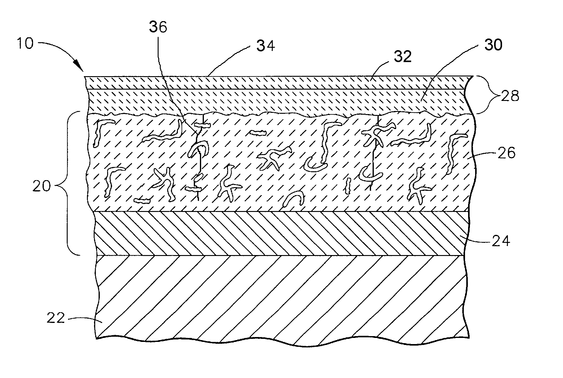
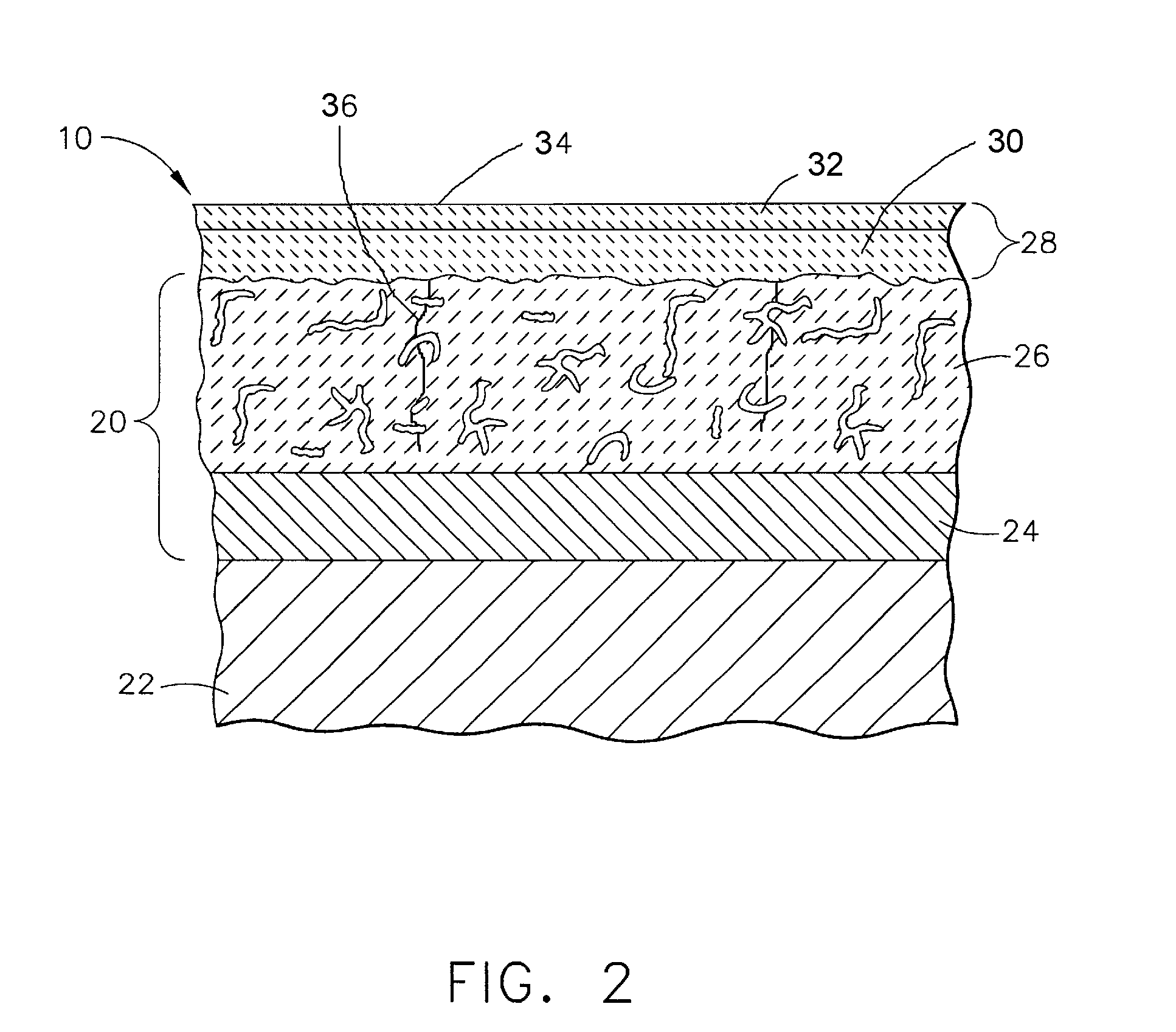
[0017] A thermal barrier coating (TBC) system 20 of a type suitable for thermally insulating the inte...


PUM

PropertyMeasurementUnit
Raaaaaaaaaaa
surface roughnessaaaaaaaaaa
weight percentaaaaaaaaaa

Abstract

A coating and method for overcoating a TBC on a component used in a high-temperature environment, such as the combustor section of an industrial gas turbine. The coating defines the outermost surface of the component and is formed of at least two layers having different compositions. An inner layer of the coating contains alumina in a first silica-containing matrix material that is free of zinc titanate. An outer layer of the coating contains alumina, a glass material, and zinc titanate in a second silica-containing matrix material. The outer layer of the coating has a surface roughness of not greater than three micrometers Ra and forms the outermost surface of the component. The coating reduces the component temperature by reducing the convective and radiant heat transfer thereto.

Description

BACKGROUND OF INVENTION [0001] 1. Field of the Invention [0002] The present invention generally relates to coatings for components exposed to high temperatures, such as the hostile thermal environment of a gas turbine. More particularly, this invention relates to a smooth outer coating for combustor components of a gas turbine component, in which the coating reduces the component temperature by reducing the convective and radiant heat transfer to the component in the combustor section of the turbine. [0003] 2. Description of the Related Art [0004] Hot section components of aircraft and industrial (power generation) gas turbine engines are often protected by a thermal barrier coating (TBC), which reduces the temperature of the underlying component substrate and thereby prolongs the service life of the component. Ceramic materials and particularly yttria-stabilized zirconia (YSZ) are widely used as TBC materials because of their high temperature capability, low thermal conductivity, a...

Claims


Application Information

Patent Timeline
Patent Type & Authority Applications(United States)
IPC IPC(8): C23C4/10C23C4/12C23C10/30C23C28/00C23C30/00
CPCC23C24/08C23C26/00C23C28/3215C23C28/3455Y10T428/252C23C28/324C23C28/345Y10T428/256Y02T50/67Y02T50/60
Inventor STOWELL, WILLIAM RANDOLPHIVKOVICH, DANIEL PETERMANNING, TIMOTHY LANCEMCGOVERN, TARA EASTERMURPHY, JANE ANNRENTZ, THOMAS WALTERROLING, MATHEW CURTISROWE, RAYMOND GRANTSKOOG, ANDREW JAY
Owner GENERAL ELECTRIC CO
Why Eureka
Try Eureka