
Imprint apparatus and method for imprinting

Active Publication Date: 2005-12-29
KK TOSHIBA
View PDF11 Cites 37 Cited by
  • Summary
  • Abstract
  • Description
  • Claims
  • Application Information

AI Technical Summary

Benefits of technology

[0013] An object of the present invention is to provide a imprint apparatus being able to fabricate with high throughput the magnetic recording medium having the patterned media.

Problems solved by technology

A magnetic recording medium at the above size cannot be fabricated by using earlier photolithography due to limits on the wavelength of light.
However, poor throughput becomes a problem.
It is difficult, with imprinting, to uniformly press a large area because of the distortions of the substrate and the stamper, or the like.
However, the distortions of both the stamper and the surface of the substrate do not sufficiently offset one another.
However, heating and cooling processes are added, causing poor throughput.
In addition, the problem of irregular imprinting caused by the distortions of the substrate and stamper or the like remains unsolved.
However, since the resist is deformed at room temperature, distortion of the resist's surface after imprinting occurs over time.
However, such transparent materials have problems with strength when being pressed under a high pressure and thus cannot be used.

Method used


Image

  • Imprint apparatus and method for imprinting
  • Imprint apparatus and method for imprinting
  • Imprint apparatus and method for imprinting

Examples


first embodiment

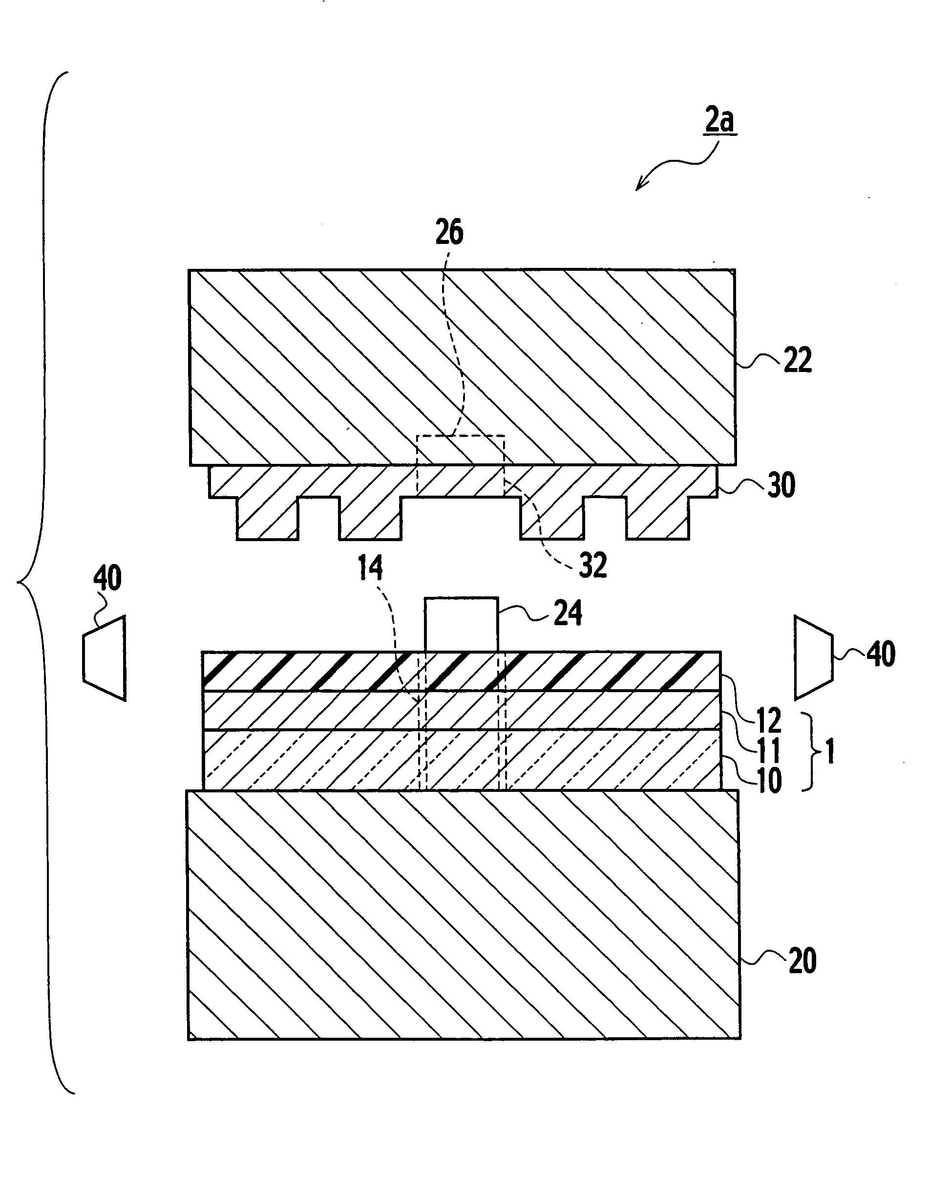
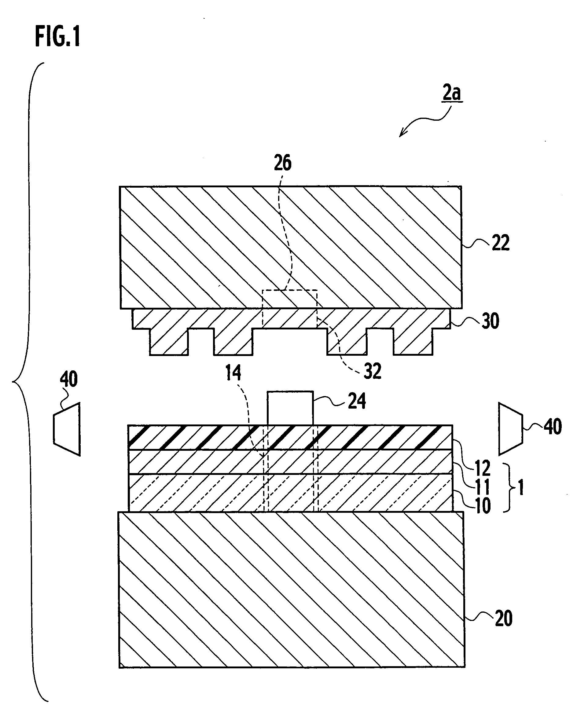
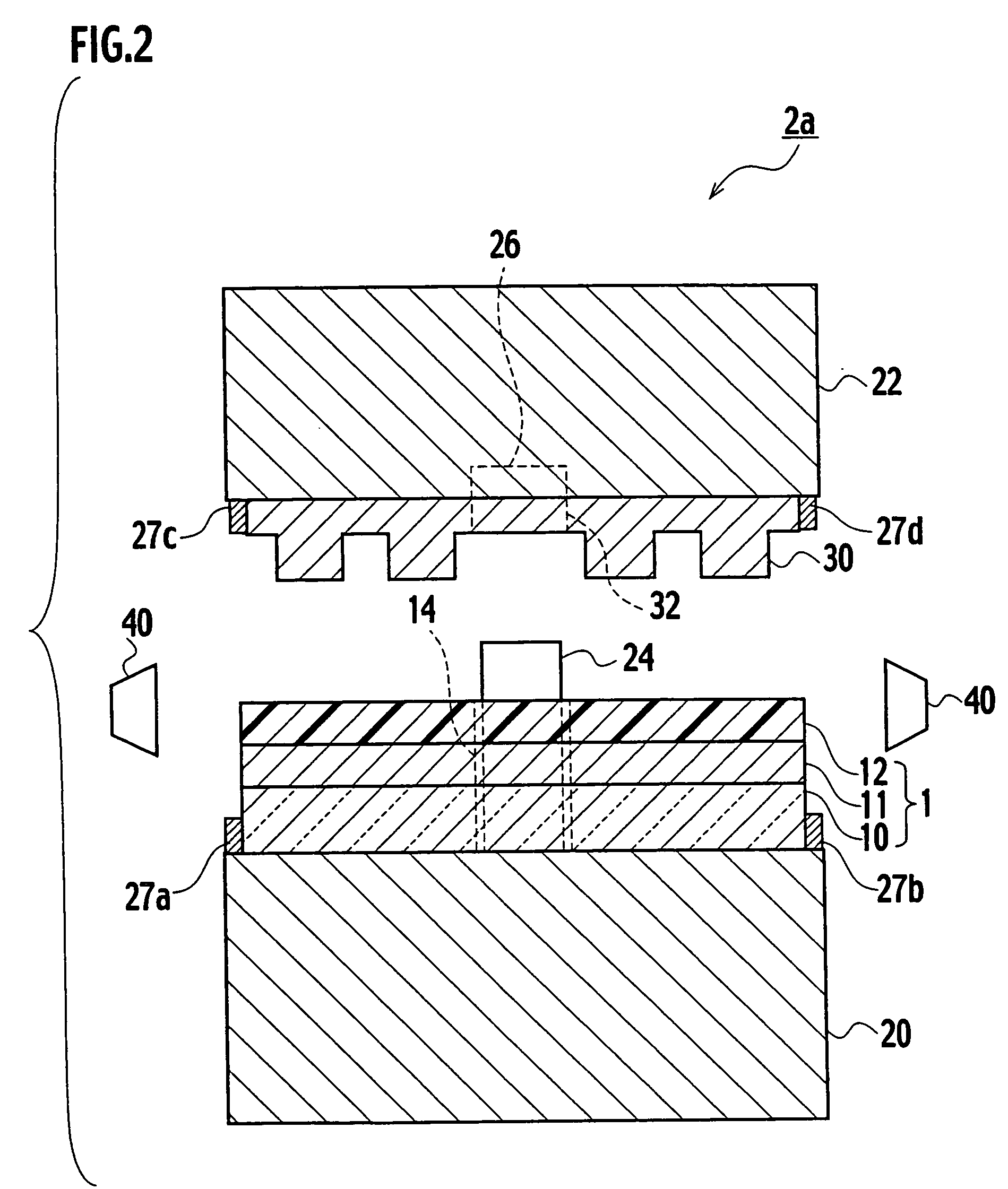
[0036] As shown in FIG. 1, an imprint apparatus 2a according to a first embodiment of the present invention includes a first press plate 20 onto which a laminate structure 1 is mounted. In the laminate structure 1, a magnetic film 11 and a resist film 12 are sequentially laminated on a substrate 10. The imprint apparatus 2a also includes a second press plate 22 facing the first press plate 20 and sandwiching the laminate structure 1 with the first press plate 20, a stamper 30 placed on a surface of the second press plate 22 facing the first press plate 20, and having projections and recesses to be transferred onto the resist film 12, and a light source 40, that surrounds and is on the same plane as, the laminate structure 1, and is oriented toward the resist film 12.

[0037] The size (diameter) of the laminate structure 1 is generally about 20 mm, 46 mm, 65 mm, 89 mm or the like. The substrate 10 is made of a high strength aluminum alloy, hardened glass or the like enables a thin-pla...

second embodiment

[0048] As shown in FIG. 10, an imprint apparatus 2b according to a second embodiment of the present invention is different from the imprint apparatus 2a shown in FIG. 1 in that the imprint apparatus 2b has a cylinder-shaped light shielding plate 42. The rest of the imprint apparatus 2b is substantially the same as the imprint apparatus 2a shown in FIG. 1, and thus duplicated descriptions will be omitted.

[0049] The light shielding plate 42 is disposed between the laminate structure 1 and the light source 40. The light shielding plate 42 blocks UV light emitted from the light source 40 from reaching the laminate structure 1, and may have any shape as long as it can control the emission of UV light onto the laminate structure 1. The light shielding plate 42 functions like an openable shutter by moving in a vertical direction or the like. Therefore the light shielding plate 42 is able to open and shut.

[0050] Hereinbelow, a method of imprinting of the imprint apparatus 2b according to ...


PUM


Abstract

An imprint apparatus configured such that it can press a laminate structure in which a magnetic film and a resist film are sequentially laminated on a substrate. The imprint apparatus includes a first press plate configured to mount the laminate structure, a second press plate adapted for sandwiching the laminate structure, a stamper placed on a surface of the second press plate, and has projections and recesses configured to be transferred onto the resist film, and a light source configured to dispose on the same plane as the laminate structure, and is oriented so that the light source can shine the resist film.

Description

CROSS REFERENCE TO RELATED APPLICATIONS [0001] This application is based upon and claims the benefit of priority from the prior Japanese Patent Application No. P2003-342067, filed on Sep. 30, 2003; the entire contents of which are incorporated herein by reference. BACKGROUND OF THE INVENTION [0002] 1. Field of the Invention [0003] The present invention relates to an imprint technique used for manufacturing information recording apparatuses, and particularly to an imprint apparatus and a method for imprinting for the processing of magnetic recording media. [0004] 2. Description of the Related Art [0005] In recent years, information recording apparatuses used in general purpose computers or the like have dealt with high capacity data including audio, video and the like, and the recording capacities thereof have thus been increased. With regard to the magnetic recording medium of hard disks and the like serving information recording apparatuses, “patterned media” has been considered fa...

Claims


Application Information

Patent Timeline
IPC IPC(8): G11B5/855B41G7/00G03F7/00
CPCB82Y10/00G11B5/855G03F7/0002B82Y40/00Y10S977/877Y10S977/888
Inventor SAKUARAI, MASATOSHIKIKITSU, AKIRAKIHARA, NAOKO
Owner KK TOSHIBA
Learn More