Floor panel structure of vehicle body

a technology of floor panels and vehicle bodies, which is applied in the direction of roofs, transportation and packaging, vehicle arrangements, etc., can solve the problems of unfavorable vehicle body weight increase, uncomfortable vibration and noise generation in the cabin, and road noise, so as to reduce the acoustic emission and reduce the vibration energy. , the effect of properly reducing the vibration energy

Inactive Publication Date: 2005-12-29
MAZDA MOTOR CORP
View PDF12 Cites 13 Cited by
  • Summary
  • Abstract
  • Description
  • Claims
  • Application Information

AI Technical Summary

Benefits of technology

[0008] The present invention has been devised in view of the above-described problems of the conventional structure, and an object of the present invention is to provide a floor panel structure of a vehicle body which can reduce properly the vibration energy transmitted from the frame members to the floor panel and thereby reduce the acoustic emission generated from the floor panel.

Problems solved by technology

It is known that vibration from frame members coupled to the engine or the suspension of the vehicle is transmitted to floor panels and makes the floor panels and air in the cabin vibrate, resulting in uncomfortable vibration and noises being generated in the cabin.
The road noise is generally caused by resonance of vehicle tires and sympathetic vibration of the suspension.
However, a large amount of these materials are generally required, and thereby the weight of the vehicle body tends to increase improperly.
This overweight would cause various disadvantages including an issue of costs.
In this case, however, the vibration with relatively high frequency tends to increase improperly instead.
Accordingly, the same problems as described above would occur inevitably.
However, in view of these limitations in vehicle-body structure or manufacturing, there exists some cases where the vehicle body panel structure disclosed in the above-described patent publication could not reduce the vibration properly.

Method used


Image

  • Floor panel structure of vehicle body
  • Floor panel structure of vehicle body
  • Floor panel structure of vehicle body

Examples


fourth embodiment

[0059] Also, according to the present invention, the vibration transmission reduction structure is provided at the No. 4 cross member 29 which is connected to the side sill 20. Accordingly, the vibration transmitted to the panel area S10, S11, S13 and S14 from the side sill 20 via the No. 4 cross member 29 is reduced. There are also provided the above-described vibration reduction structure at the panel area S10 and S11.

[0060] Herein, the vibration transmission reduction structure will be described. The vibration transmission reduction structure is that a specified low-rigidity area having a low rigidity is provided near a connecting portion of the cross member with the side frames, such as the side sill 20, floor side frame 22 and rear side frame. The side frame generally generates a torsional vibration with deformation to be slant laterally and or a bending vibration with a deformation to be bent longitudinally, and thereby the low-rigidity area at the cross member tends to be def...

first embodiment

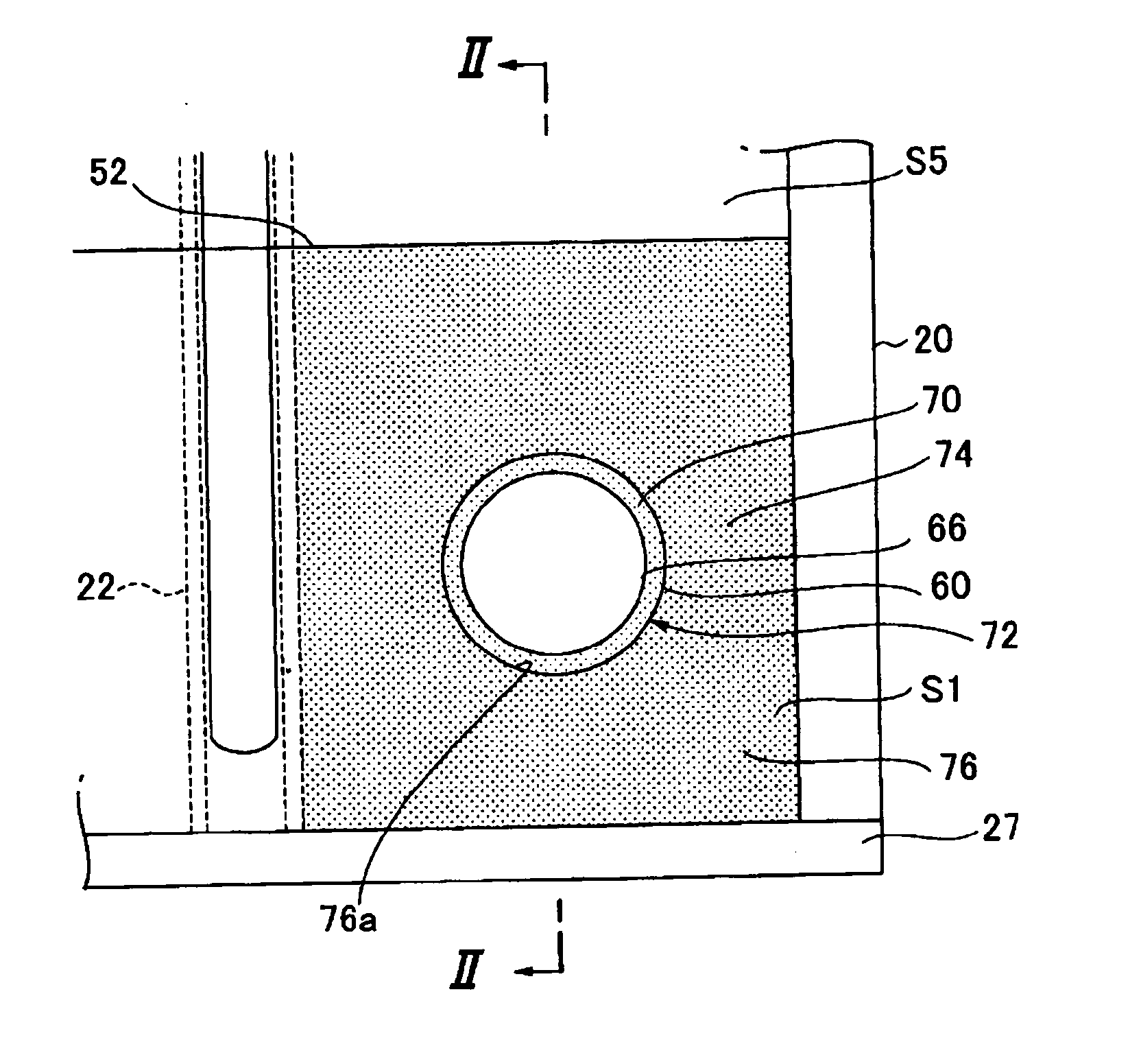
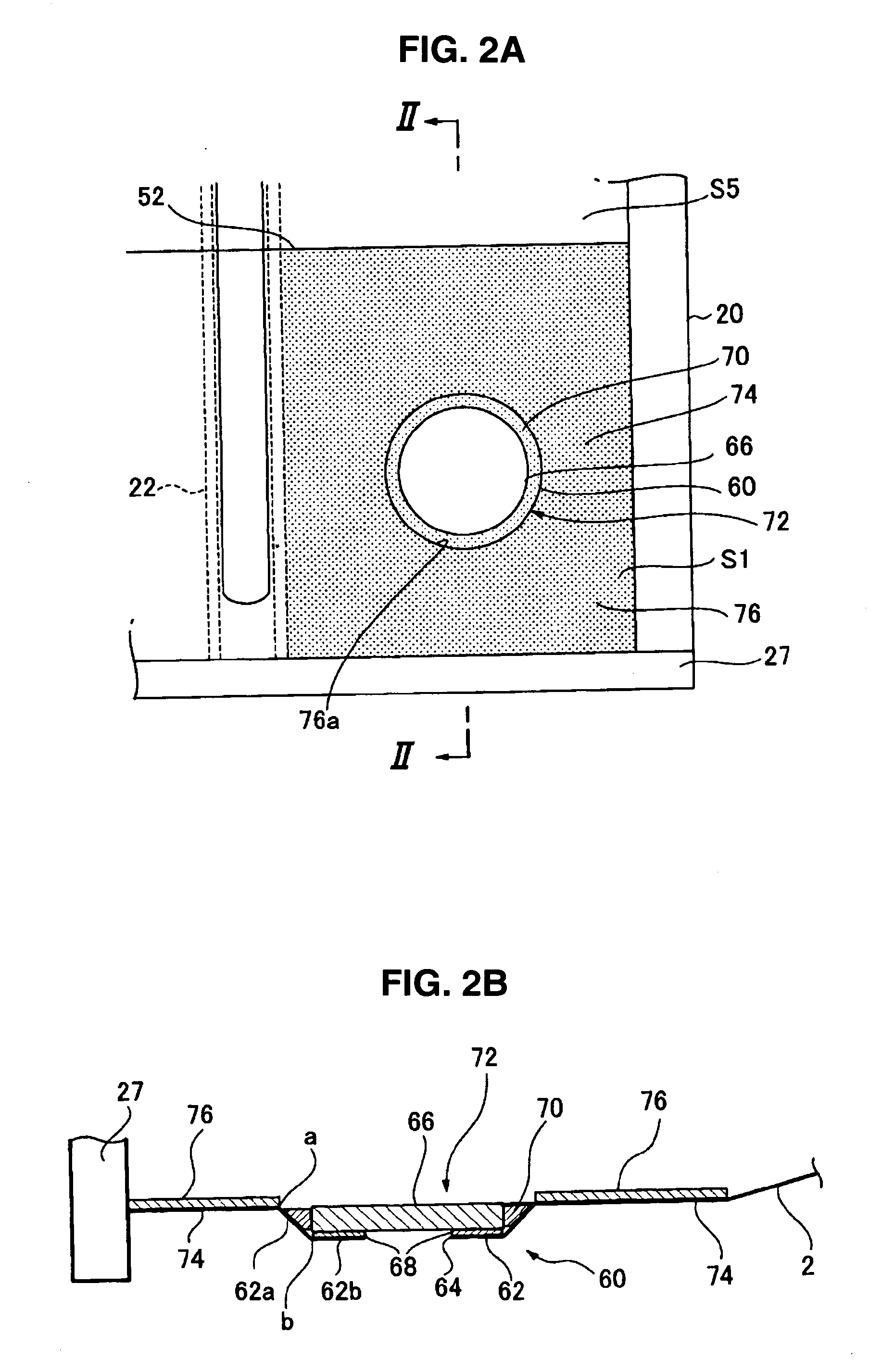
[0071] Next, the function and effect of the floor panel structure will be described. Since the high-rigidity area 72 comprising the plug 66 and the opening portion 60 and the low-rigidity area 74 being provided around the high-rigidity area 72 are formed within the panel area S1, S4, S9 and S12 of the floor panel structure, the vibration energy is increased at the low-rigidity area 74 due to the difference in rigidity between the high-rigidity area 72 and the low-rigidity area 74. Further, since the high-rigidity area 72 also constitutes the heavy-weight area 72 which is made heavier per unit area than the low-rigidity area 74 by the plug 66 and the low-rigidity area 74 also constitutes the light-weight area (the peripheral area) 74, the vibration energy is further increased at the light-weight area (the peripheral area) 74 due to this difference in weight between the heavy-weight area 72 and the light-weight area 74.

[0072] The vibration energy being properly increased at the low-r...

second embodiment

[0085] Next, the function and effect of the floor panel structure will be described. Since there are provided the high-rigidity area 82 having the damping material 80 and the low-rigidity area 84 being provided around the high-rigidity area 82 within the panel area S2 and S3, the vibration energy is increased at the low-rigidity area 84 due to the difference in rigidity between the high-rigidity area 82 and the low-rigidity area 84. Further, since the high-rigidity area 82 also constitutes the heavy-weight area 82 which is made heavier per unit area than the peripheral area 84 by the damping material 80, the vibration energy is further increased at the light-weight area (the peripheral area) 84 due to this difference in weight between the heavy-weight area 82 and the light-weight area 84.

[0086] The vibration energy being properly increased at the low-rigidity area (light-weight area) 84 is transformed to the thermal energy by the damping effect of the steel plate forming the floor ...


PUM


Abstract

In a floor panel structure of a vehicle body in which a floor of an automotive vehicle is formed by a floor panel coupled to a plurality of frame members extending in substantially longitudinal and width directions of the vehicle, there are provided a panel area formed by being enclosed at least by the frame members, a heavy-weight area located at a substantially central portion of the panel area, and a peripheral area located substantially around the heavy-weight area, wherein the heavy-weight area is configured so as to be heavier than the peripheral area. Accordingly, the vibration energy transmitted from the frame members to the floor panel can be reduced and thereby the acoustic emission generated from the floor panel can be reduced.

Description

BACKGROUND OF THE INVENTION [0001] The present invention relates to a floor panel structure of a vehicle body, particularly to a floor panel structure of a vehicle body in which a floor of an automotive vehicle is formed by a floor panel coupled to a plurality of frame members which extend in substantially longitudinal and width directions of the vehicle body. [0002] It is known that vibration from frame members coupled to the engine or the suspension of the vehicle is transmitted to floor panels and makes the floor panels and air in the cabin vibrate, resulting in uncomfortable vibration and noises being generated in the cabin. Herein, the vibration of engine itself and the road noise from the suspension are considered as vibration resources primarily. The road noise is generally caused by resonance of vehicle tires and sympathetic vibration of the suspension. [0003] Conventionally, damping materials or the like which are applied to the floor panels or the particular portions of th...

Claims


Application Information

Patent Timeline
Patent Type & Authority Applications(United States)
IPC IPC(8): B60R13/08B62D25/20
CPCB60R13/083B62D25/2036B62D25/20
Inventor SUGIHARA, TSUYOSHINAKABAYASHI, SEIICHIHIRABAYASHI, SHIGEFUMI
Owner MAZDA MOTOR CORP
Why Eureka
Try Eureka