
Crystal oscillator

a crystal oscillator and oscillator technology, applied in the field of crystal oscillators, can solve the problems of reducing temperature stability, requiring smaller power consumption and shorter warm-up time, and large power consumption, and achieves stable oscillation frequency, reduce power consumption, and facilitate mass production

Inactive Publication Date: 2005-12-29
NIHON DEMPA KOGYO CO LTD
View PDF10 Cites 20 Cited by
  • Summary
  • Abstract
  • Description
  • Claims
  • Application Information

AI Technical Summary

Benefits of technology

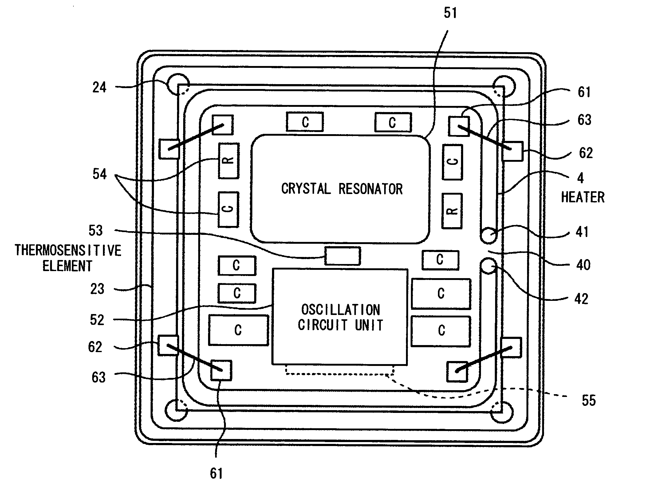
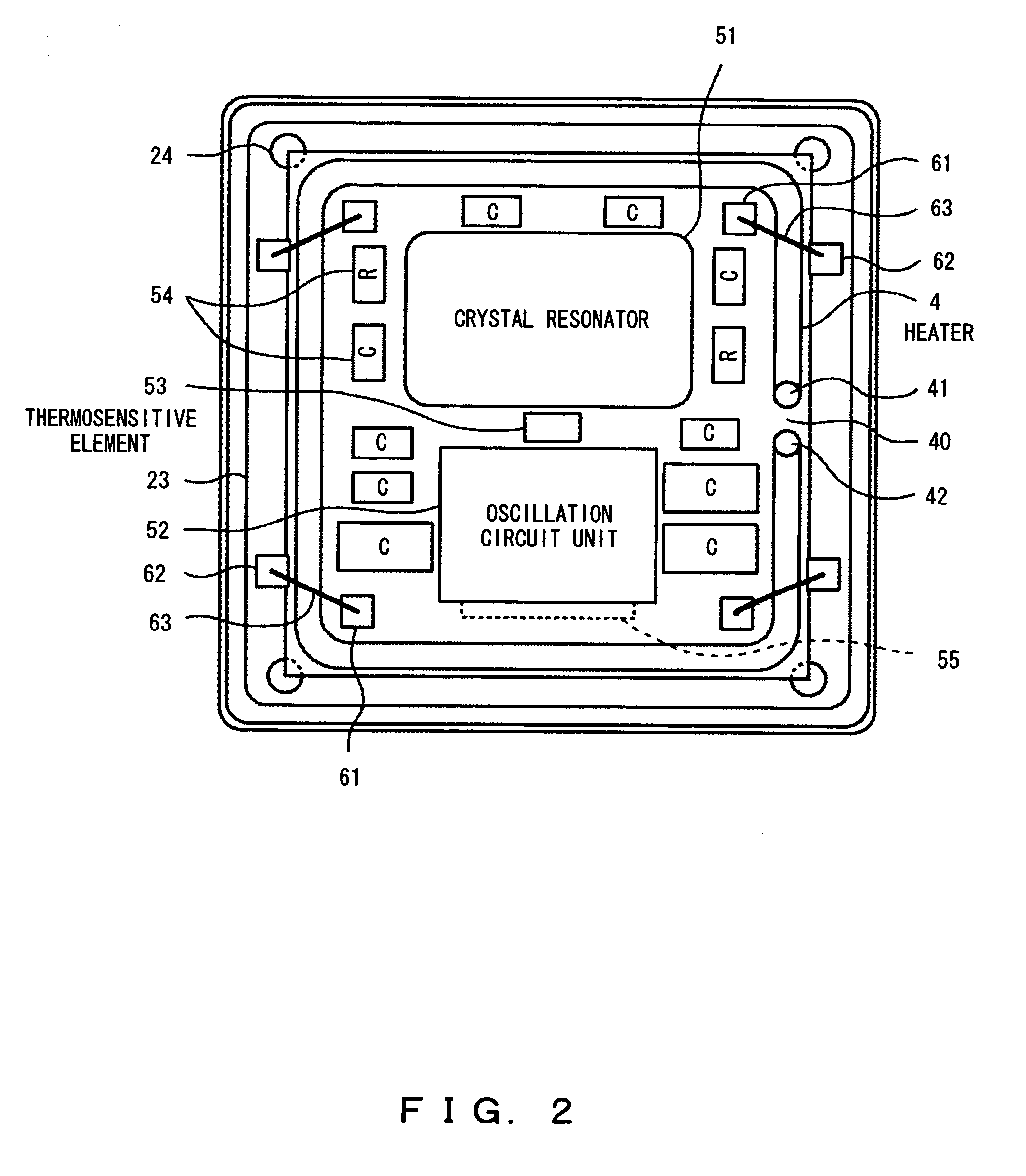
The present invention aims to provide a crystal oscillator that can be easily mass-produced, reduce power consumption, and be stable in oscillation frequency to ambient temperature variations. The invention includes a substrate, a heating device, a crystal resonator and an oscillation circuit unit, a thermosensitive element, and a control unit for controlling the heating value applied to the heating device. The heating device surrounds the crystal resonator and the oscillation circuit unit, reducing the impact of ambient temperature variations and stabilizing the temperature characteristic of the frequencies. This results in a small change in oscillation frequency of the crystal oscillator by the ambient temperature variations, reducing the amount of heating required and power consumption. The heating device can be formed as a resistance heater layer or a belt-shaped device. The method of manufacturing the crystal oscillator includes arranging a heating device and arranging a crystal resonator or a crystal element, an oscillation circuit unit, a thermosensitive element, and a control unit in the area enclosed by the heating device.

Problems solved by technology

The OCXO type encloses a crystal element and a peripheral circuit in a package, and the entire package is covered with a heater, thereby stabilizing the temperature of the crystal element to the ambient temperature variations and excelling in the temperature characteristic, but having the disadvantage of large power consumption and long warm-up time.
On the other hand, the TCXO type is provided with an temperature characteristic compensation circuit in a peripheral circuit to compensate for an oscillation frequency based on the temperature detection value of a thermosensitive element, thereby requiring smaller power consumption and shorter warm-up time than the OCXO type, but having lower temperature stability.
However, the crystal oscillator of the patent document 1 has the following problems.
Therefore, when a practical operation is performed, the crystal oscillator cannot be guaranteed as a stable device.

Method used


Image

  • Crystal oscillator
  • Crystal oscillator
  • Crystal oscillator

Examples


Embodiment Construction

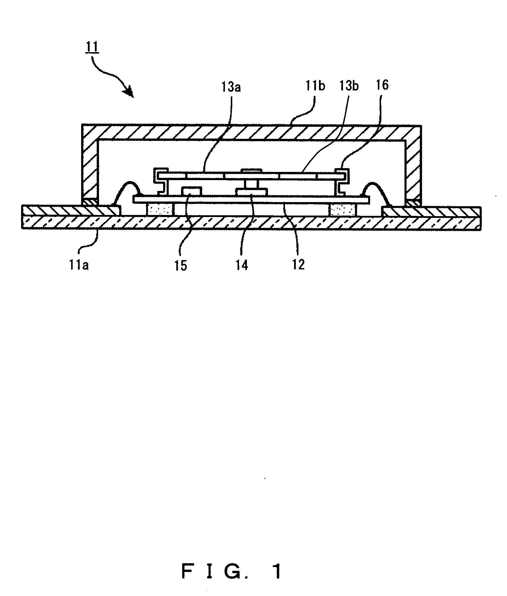
[0025]FIGS. 2 and 3 are respectively a cross-sectional plan view and a sectional side view of the crystal oscillator according to an embodiment of the present invention. In FIG. 3, a package 2 is a container (package) of airtight structure configuring an external structure of a crystal oscillator. The package 2 is configured by a box-shaped and open-top base 21 of material of low thermal conductivity, for example, ceramics, and a cover unit 22 of, for example, a metal plate covering the top of the base 21 using an adhesive 20. The package 2 is vacuum-sealed in this example to make a heat insulating structure to an external unit. The base 21 contains a step unit 23 along the entire circumference. On the step unit 23, a circumference unit of a substrate 3 of a material of low thermal conductivity, for example, glass is supported through an adhesive 24. Instead of supporting the entire circumference of the substrate 3 using the base 21, a point supporting structure such as a glass stud...


PUM


Abstract

A crystal oscillator of the present invention includes: a substrate provided in a package; a heating device arranged as surrounding an internal area of the substrate on at least one of the surfaces of the substrate; a crystal resonator or a crystal element and an oscillation circuit unit provided in an area enclosed by the heating device; a thermosensitive element which detects a temperature in an area enclosed by the heating device; and a control unit for controlling a heating value applied to the heating device based on a detection result of the thermosensitive element.

Description

BACKGROUND OF THE INVENTION [0001] 1. Field of the Invention [0002] The present invention relates to a crystal oscillator for stabilizing the frequency to the ambient temperature variations using a thermosensitive element and a heating device. [0003] 2. Description of the Related Art [0004] A crystal oscillator for stabilizing the frequency to ambient temperature variations can be of well-known OCXO (oven-controlled crystal oscillator) and TCXO (temperature compensated crystal oscillator) types. The OCXO type encloses a crystal element and a peripheral circuit in a package, and the entire package is covered with a heater, thereby stabilizing the temperature of the crystal element to the ambient temperature variations and excelling in the temperature characteristic, but having the disadvantage of large power consumption and long warm-up time. On the other hand, the TCXO type is provided with an temperature characteristic compensation circuit in a peripheral circuit to compensate for ...

Claims


Application Information

Patent Timeline
Patent Type & Authority Applications(United States)
IPC IPC(8): H03B5/04H10N30/00H03B5/32H03H9/02H03H9/05H03H9/10H03L1/04
CPCH03B5/32H03H9/02102H03H9/0528H03L1/04H03H9/0552H03H9/1014H03H9/0542
Inventor OITA, TAKEOFUKUDA, MINORU
Owner NIHON DEMPA KOGYO CO LTD
Learn More