Contact hole printing method and apparatus with single mask, multiple exposures, and optimized pupil filtering

a printing method and contact hole technology, applied in the field of manufacturing processes, can solve the problems of increasing the cost of the lithographic process, reducing the throughput of the exposure tool, and reducing the depth of focus (dof) to approximately half that of a single exposure process, so as to achieve the effect of optimizing the pupil filtering, reducing the impact of throughput, and improving the depth of focus

Inactive Publication Date: 2005-12-29
IBM CORP
View PDF12 Cites 19 Cited by
  • Summary
  • Abstract
  • Description
  • Claims
  • Application Information

AI Technical Summary

Benefits of technology

[0007] The present invention provides a lithographic process and apparatus (e.g., for printing contact holes on a wafer) that use a single mask, multiple exposures, and optimized pupil filtering. In particular, a multiple (e.g., double) exposure technique with single mask is used with optimized source and pupil filtering to improve depth-of-focus (DOF) with minimum throughput impact and no extra mask cost.

Problems solved by technology

This prior art method is problematic in that it requires that two masks be fabricated for each overall circuit pattern.
This increases the cost of the lithographic process.
Unfortunately, when two masks are used, the mask cost is doubled and throughput of the exposure tool is reduced to approximately half that of a single exposure process.
Both of these factors result in severe increases of the cost of processing.
This common phase runout against the axis increases depth of focus, but causes increased image background at large distances from the geometrical image point.
As a result, the traditional pupil filter works well for printing isolated contacts, but performs poorly with dense contacts (small to moderate pitches).
Even with such filters, this prior art pupil-filtering method does not provide coverage of as wide a pitch range as is desired in many applications.
These assist features reduce pupil intensity in orders that increase error sensitivity, but they cannot fully block out those orders, since the assist features must be held well below the printing resolution of the lithographic process.
As such, sub-resolution assist features are very sensitive to mask fabrication error.

Method used


Image

  • Contact hole printing method and apparatus with single mask, multiple exposures, and optimized pupil filtering
  • Contact hole printing method and apparatus with single mask, multiple exposures, and optimized pupil filtering
  • Contact hole printing method and apparatus with single mask, multiple exposures, and optimized pupil filtering

Examples


Embodiment Construction

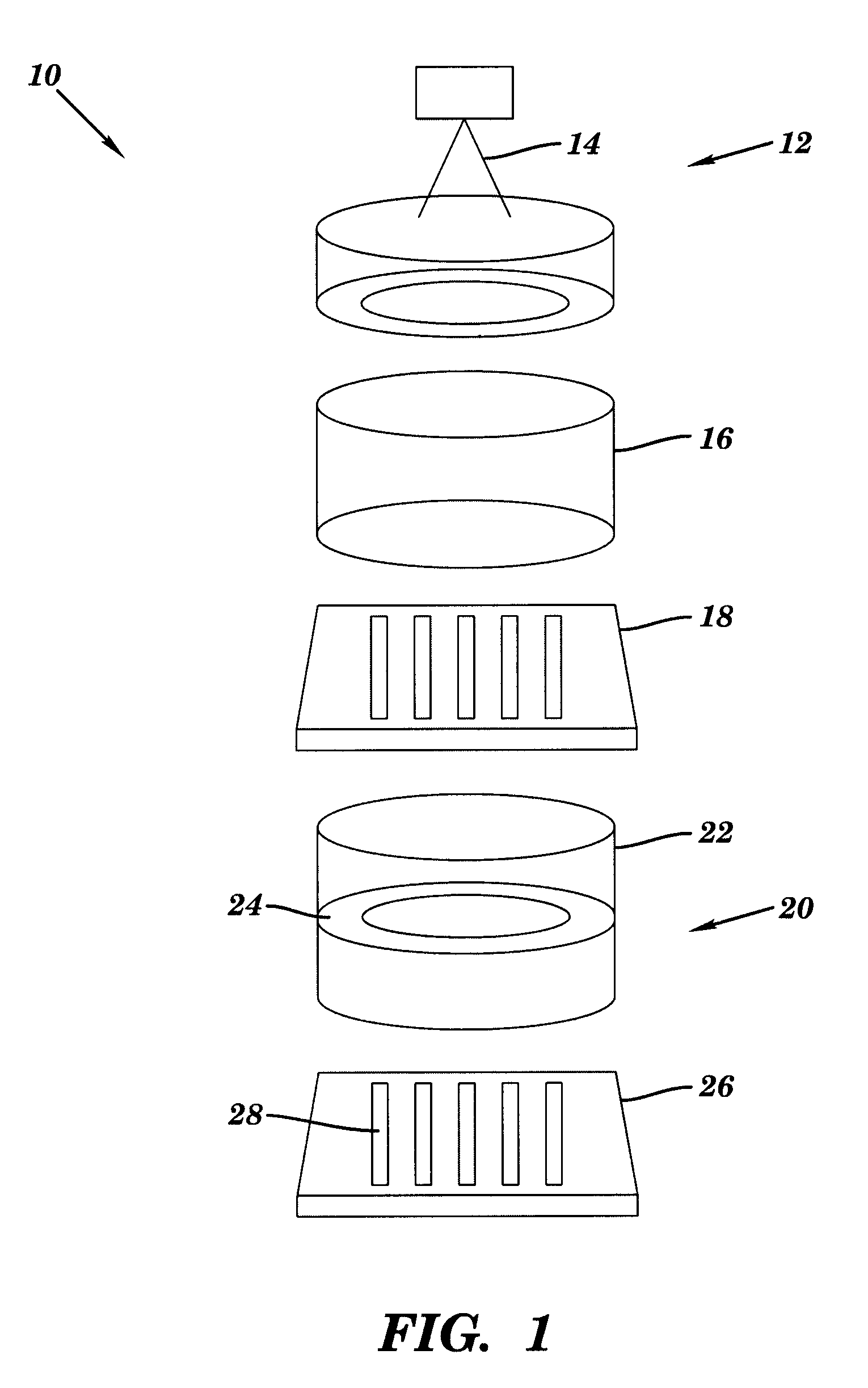
[0023]FIG. 1 schematically illustrates a lithographic system 10 in accordance with an embodiment of the present invention. The lithographic system 10 includes an illumination system 12 for providing multiple types of illumination 14. The illumination 14 is collected by a condenser lens 16 and directed to a mask or reticle 18. After passing through the mask 18, the light is collected by a projection lens system 20 comprising a projection lens 22 and a pupil filter 24, and projected to a semiconductor wafer 26 to print features 28 on the wafer 26. It is assumed for the purposes of this description that the reader has an understanding of lithographic systems commensurate with one skilled in the art. Accordingly, a detailed description of the operation of the various components of the lithographic system 10 is not presented herein.

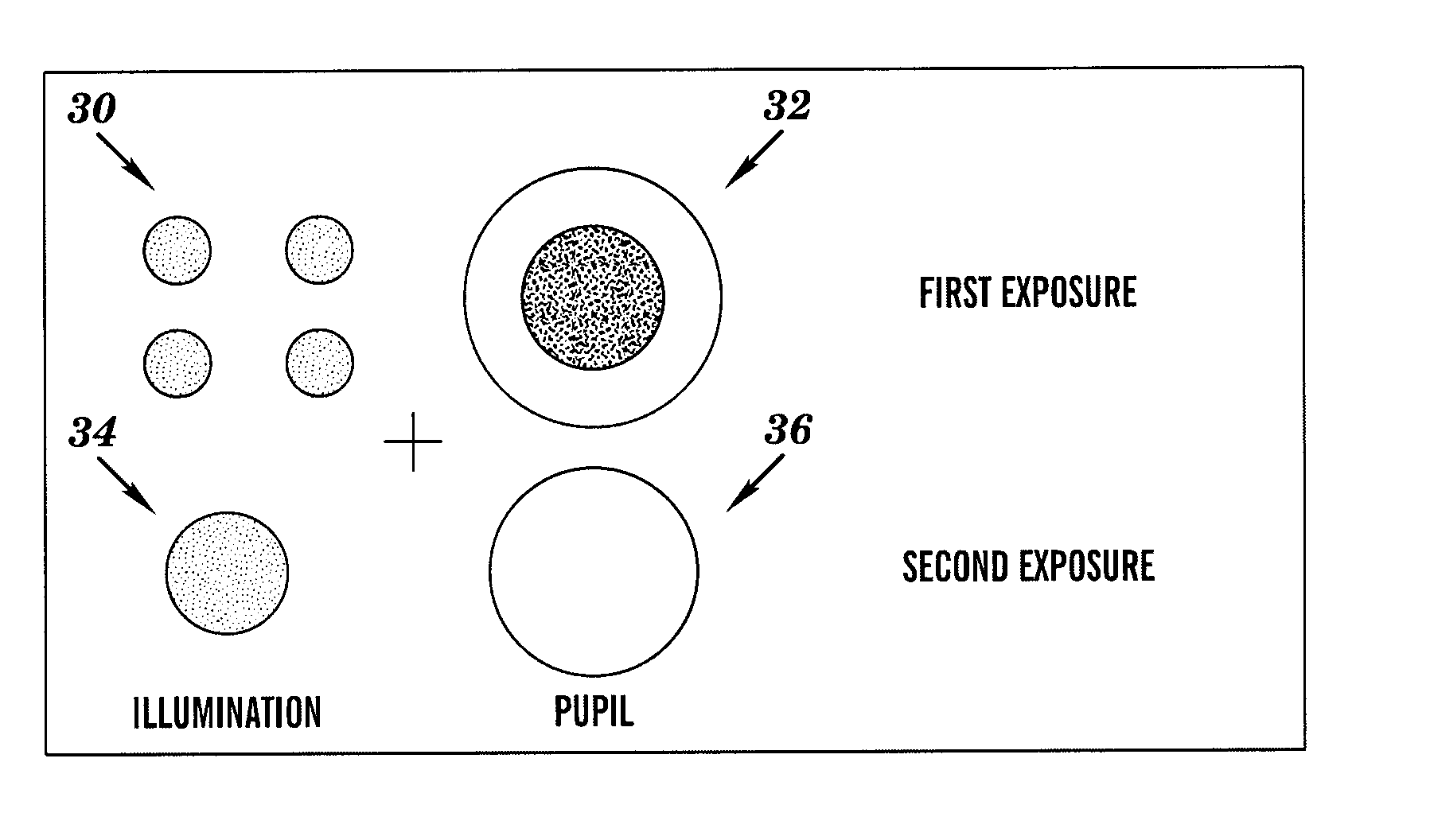
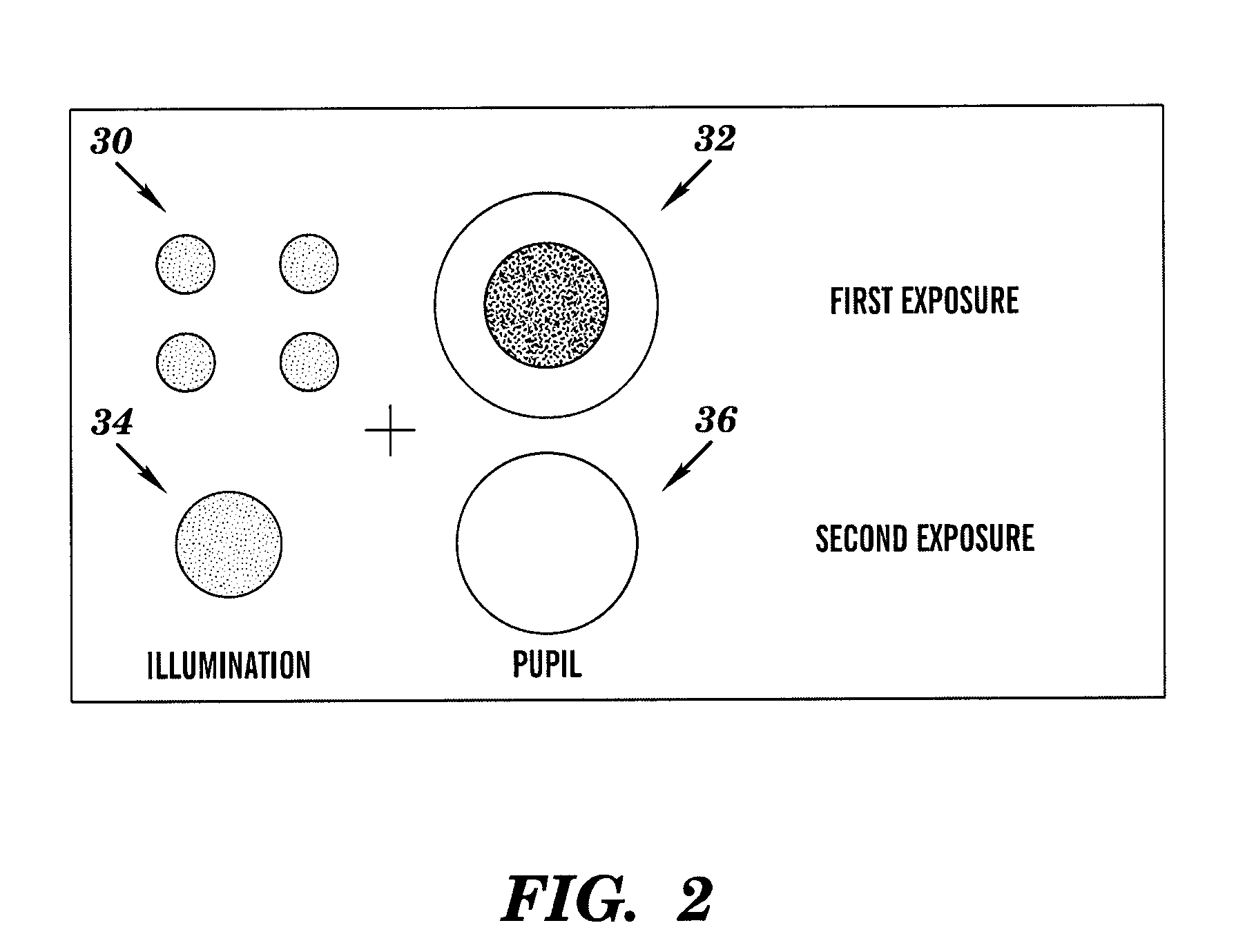
[0024] Referring now to FIG. 2, in conjunction with FIG. 1, there are illustrated the illumination and pupil filter types used in the practice of a preferred...


PUM

PropertyMeasurementUnit
radius NAobaaaaaaaaaa
radiusaaaaaaaaaa
wavelengthaaaaaaaaaa

Abstract

The present invention provides a lithographic method and apparatus (e.g., for printing contact holes on a wafer) that use a single mask, multiple exposures, and optimized pupil filtering. The method comprises: providing a mask including pattern features to be transferred to a wafer; transferring a first set of pattern features from the mask to the wafer using a first type of illumination and a first type of pupil filter; and transferring a second set of pattern features from the mask to the wafer using a second type of illumination and a second type of pupil filter.

Description

BACKGROUND OF INVENTION [0001] The present invention relates generally to manufacturing processes that require lithography and, in particular, to a contact hole printing method and apparatus that use a single mask, multiple exposures, and optimized pupil filtering. [0002] There are several lithographic techniques that are aimed at addressing the error sensitivity of contact hole patterns. One such technique requires the exposure of multiple masks. For example, a circuit pattern is divided into two separate masks, and the numerical aperture (NA) and illumination are optimized for each of these masks during each of two exposures. This prior art method is problematic in that it requires that two masks be fabricated for each overall circuit pattern. This increases the cost of the lithographic process. [0003] The double exposure / double mask technique described above is probably the best performing method known in the art to extend minimum printable pitch and / or improve critical dimension...

Claims


Application Information

Patent Timeline
Patent Type & Authority Applications(United States)
IPC IPC(8): G03C5/00G03F1/14G03F7/20
CPCG03F1/144G03F7/70466G03F7/70308G03F7/70125G03F7/70566
Inventor LERCEL, MICHAELROSENBLUTH, ALAN E.SEONG, NAKGEUON
Owner IBM CORP
Why Eureka
Try Eureka