Screening method and device, and new drug screening method and device

a screening method and a technology for drugs, applied in the field of new drug screening methods and devices, can solve problems such as screening devices, and achieve the effect of good sn ratio and high speed

Inactive Publication Date: 2005-12-29
YOKOGAWA ELECTRIC CORP
View PDF19 Cites 1 Cited by
  • Summary
  • Abstract
  • Description
  • Claims
  • Application Information

AI Technical Summary

Benefits of technology

[0013] An object of the present invention is to solve such problems and provide a screening method and device able to obtain the entire image of the cell as a detailed and accurate (with a good SN ratio) image at high speed by observing the cell image while a Nipkow system confocal scanner is used and the focal position of the objective lens is changed in the optical axis direction.
[0014] Another object of the present invention is to provide a screening device which, by reducing the amount of irradiating light of the excitation light, does not produce a negative influence by the excitation light on the cell.
[0015] Another object of the present invention is to provide a new drug screening device able to observe the entire image of the cell with high resolution and a high degree of accuracy by observing the cell image while a Nipkow system confocal scanner is used and the focal position of the objective lens is changed in the optical axis direction, and able to judge the degree of activity of the cell from the obtained image, and display a judging result in an easily recognizable display format.
[0017] Another object of the present invention is to provide a new drug screening device for calculating an optical flow from a time differential image by an arithmetic operation, and able to determine the degree of activity of the cell by making an inference for distinguishing circulatory activity within the cell and a Brownian movement on the basis of this calculation.
[0018] Further, still another object of the present invention is to provide a new drug screening device able to simply mark a target well so as to easily find the optimum well, the worst well, and so on, from the plate after measurement.
[0019] Further, another object of the present invention is to provide a new drug screening device having no negative influence by the excitation light on the cell by reducing the irradiating light amount.

Problems solved by technology

However, such screening devices have the following problems.

Method used


Image

  • Screening method and device, and new drug screening method and device
  • Screening method and device, and new drug screening method and device
  • Screening method and device, and new drug screening method and device

Examples


Embodiment Construction

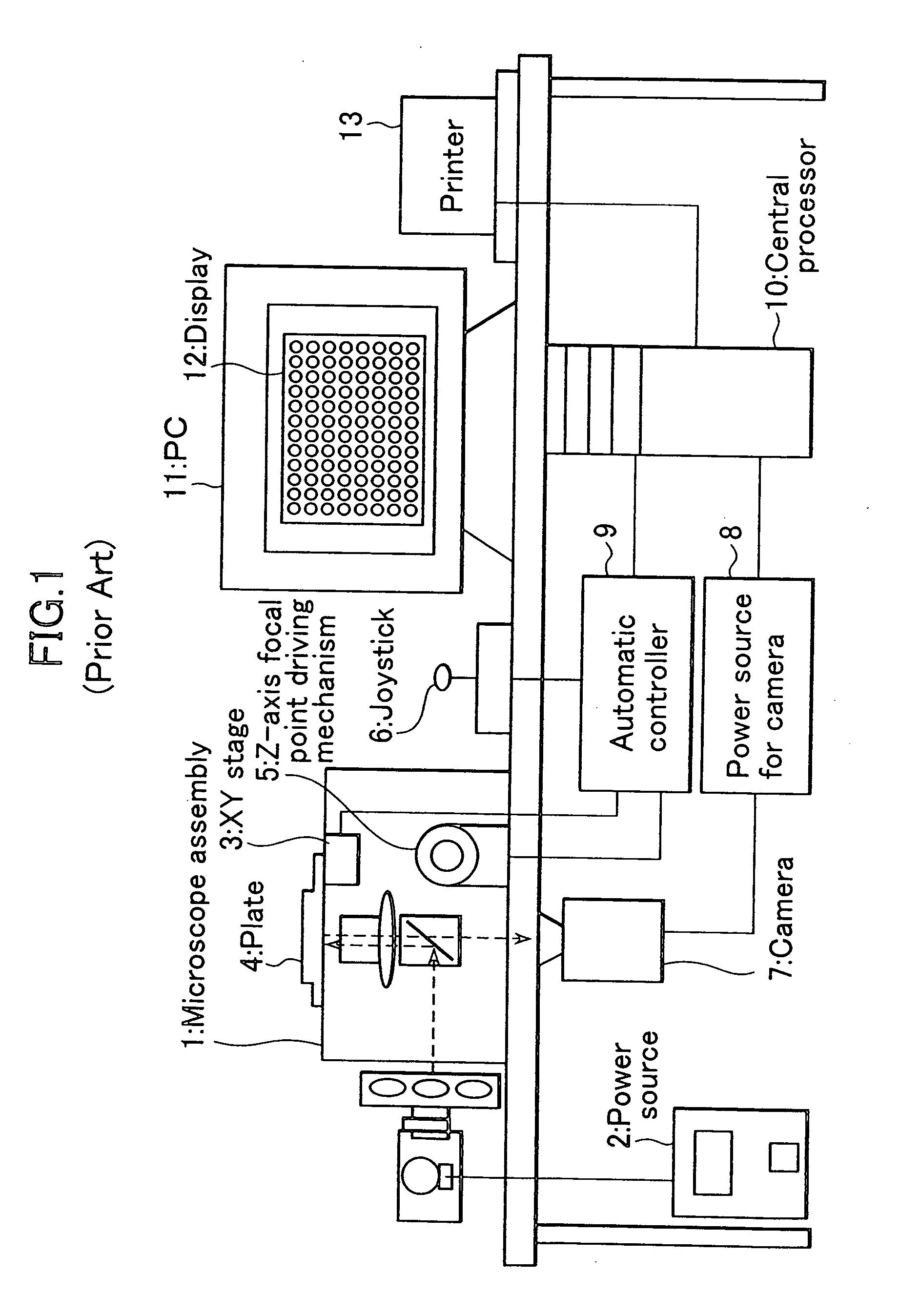
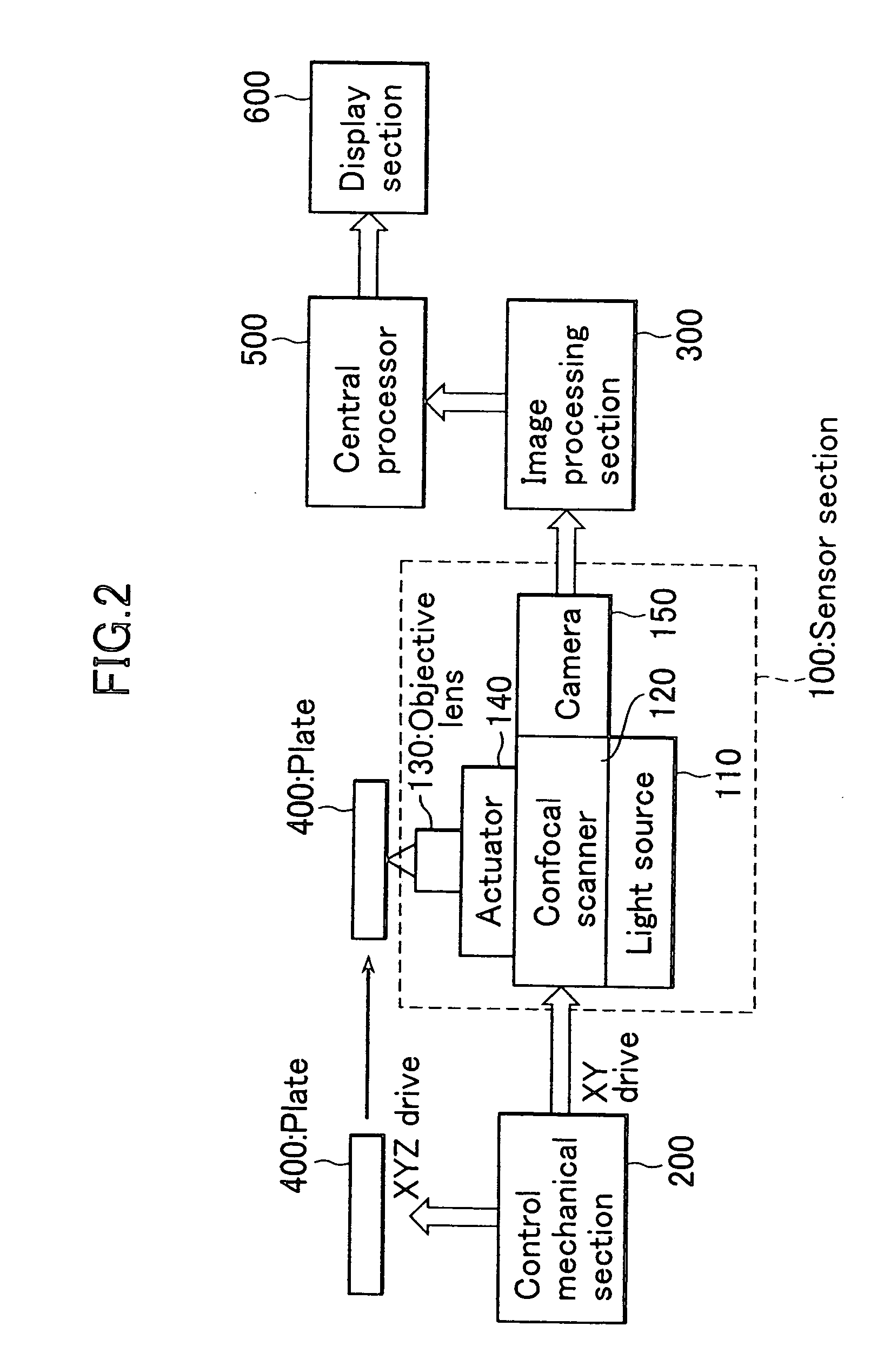
[0030] Next, the present invention will be explained in detail using the drawings. FIG. 2 is a constructional view showing one embodiment of a screening device in the present invention. In FIG. 2, reference numerals 100, 200, and 300, designate a sensor section, a control mechanical section, and an image processing section respectively. Reference numerals 400, 500, and 600, designate a plate (corresponding to plate 4 of FIG. 1), a central processing unit, and a display section respectively.

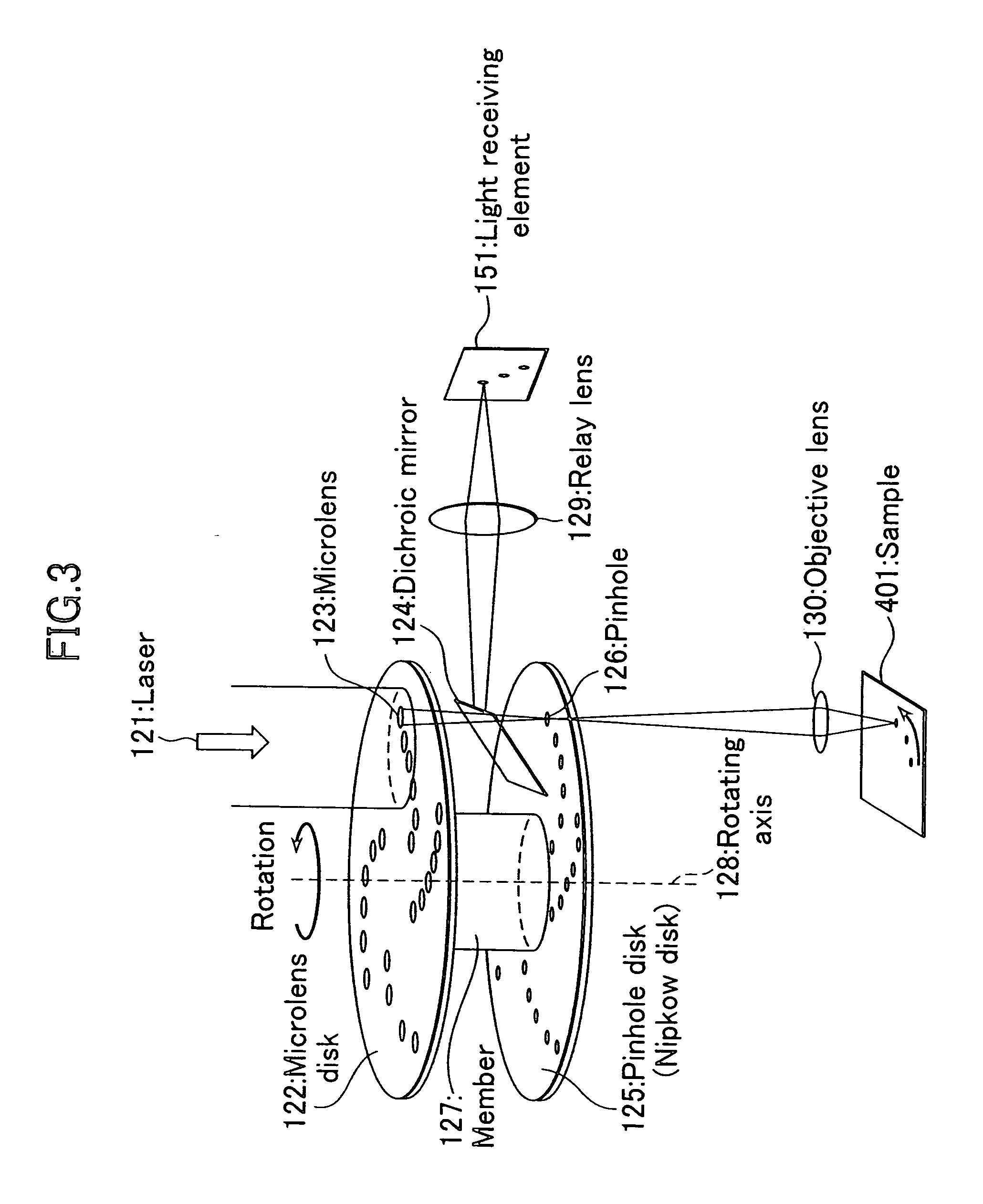
[0031] Sensor section 100 is constructed from laser light source 110, Nipkow system confocal scanner 120, objective lens 130, focal position variable means 140 and camera 150.

[0032] A laser beam as excitation light generated from laser light source 110 is converged onto a sample of plate 400 by objective lens 130 through Nipkow system confocal scanner 120. Fluorescent light from the sample excited by the laser beam is returned to confocal scanner 120 via objective lens 130, and is inputted to ca...


PUM

PropertyMeasurementUnit
fluorescentaaaaaaaaaa
fluorescent imageaaaaaaaaaa
optical axisaaaaaaaaaa

Abstract

The present invention realizes a screening method and device able to obtain the entire image of a cell as a detailed and accurate (with a good SN ratio) image at high speed by observing the cell image while a Nipkow system confocal scanner is used and the focal position of an objective lens is changed in the optical axis direction. In the present invention, a reagent and a fluorescent marked cell are injected into a well. The focal position is changed in the optical axis direction by using the Nipkow system confocal scanner. Excitation light is irradiated to the well in each focal position, and fluorescent light generated from the cell is received and the degree of activity, and so on, of the cell is measured and displayed on the basis of a slice image of the cell.

Description

BACKGROUND OF THE INVENTION [0001] 1. Field of the Invention [0002] The present invention relates to a screening method and device used in the discovery of a drug, or drug discovery for developing a new kind of medical product, and so on. [0003] 2. Description of the Prior Art [0004] For example, a device for screening a cell processed by a fluorescent reagent, and so on, and described in International Patent Publication No. 2002-525603 (International Laid-Open No. WO00 / 17643) is well known as a screening device of this kind. [0005]FIG. 1 is a constructional view of the screening device described in patent literature 1. This device uses a standard objective lens having a magnification power of 1 to 100 in comparison with a camera lens, and an inverted type fluorescent microscope 1 such as a Zeiss Axiovert inverted type fluorescent microscope using a light source (e.g. a 100 W mercury-arc lamp or 75 W xenon lamp) with power source 2. XY stage 3 for moving plate 4 in the XY directions...

Claims


Application Information

Patent Timeline
Patent Type & Authority Applications(United States)
IPC IPC(8): G01N21/64G01N33/50
CPCG01N21/6408G01N21/6428G01N21/6452G02B21/0076G01N33/5008G01N33/502G02B21/0044G01N21/6458
Inventor UCHIDA, ISAOMIKURIYA, KENTASUZUKI, TOSHIYUKIIINO, TOSHIOAKIYAMA, TAKASHI
Owner YOKOGAWA ELECTRIC CORP
Why Eureka
Try Eureka