

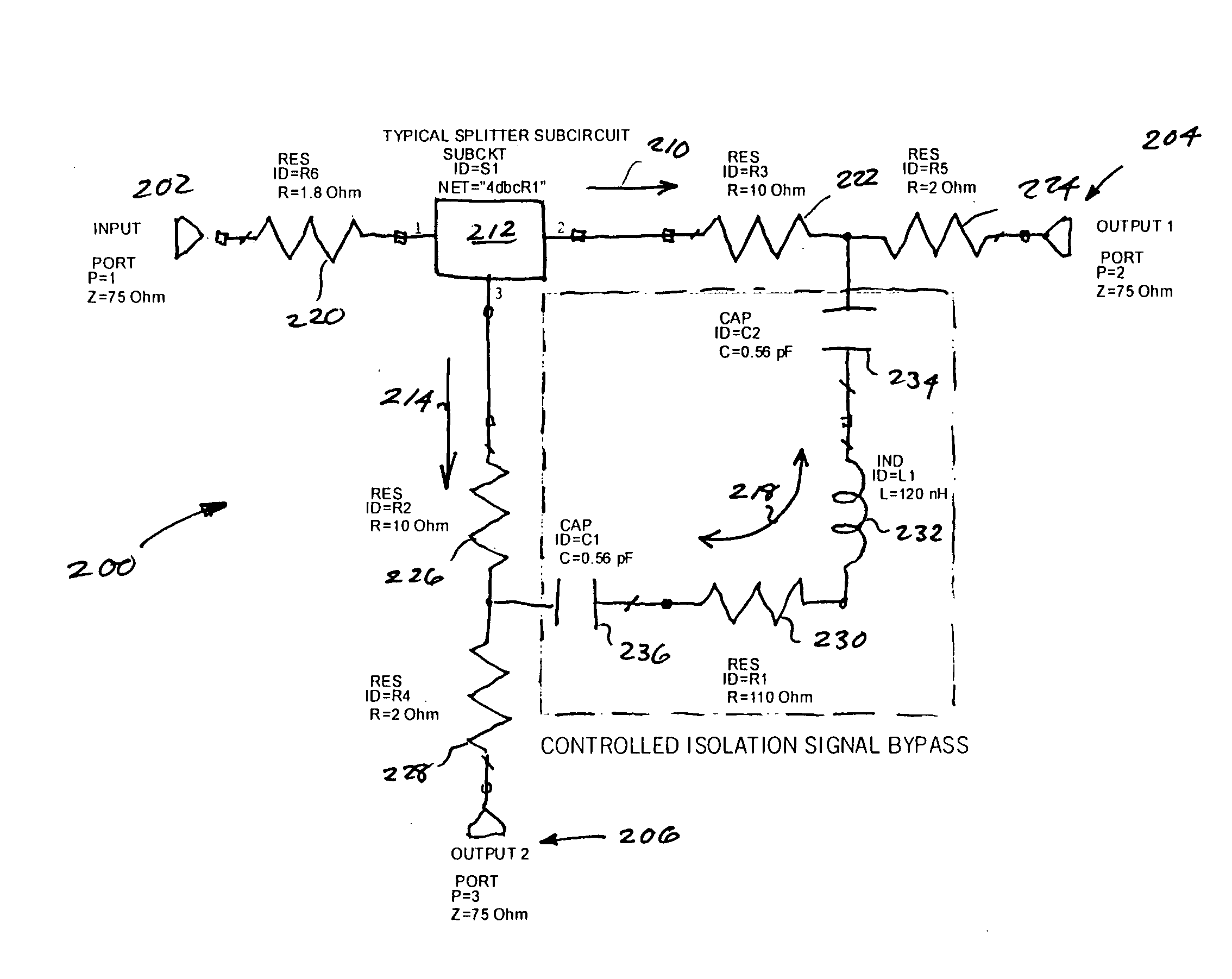
Controlled isolation splitter apparatus and methods
a splitter and control technology, applied in the field of networks, can solve the problems of transmission loss or insertion loss, power loss associated with signal transmission along the cable, and power loss is greater, and achieve the effect of reducing isolation loss and reducing isolation loss
- Summary
- Abstract
- Description
- Claims
- Application Information
AI Technical Summary
Benefits of technology
Problems solved by technology
Method used
Image

Examples
Embodiment Construction
[0054] Reference is now made to the drawings wherein like numerals refer to like parts throughout.
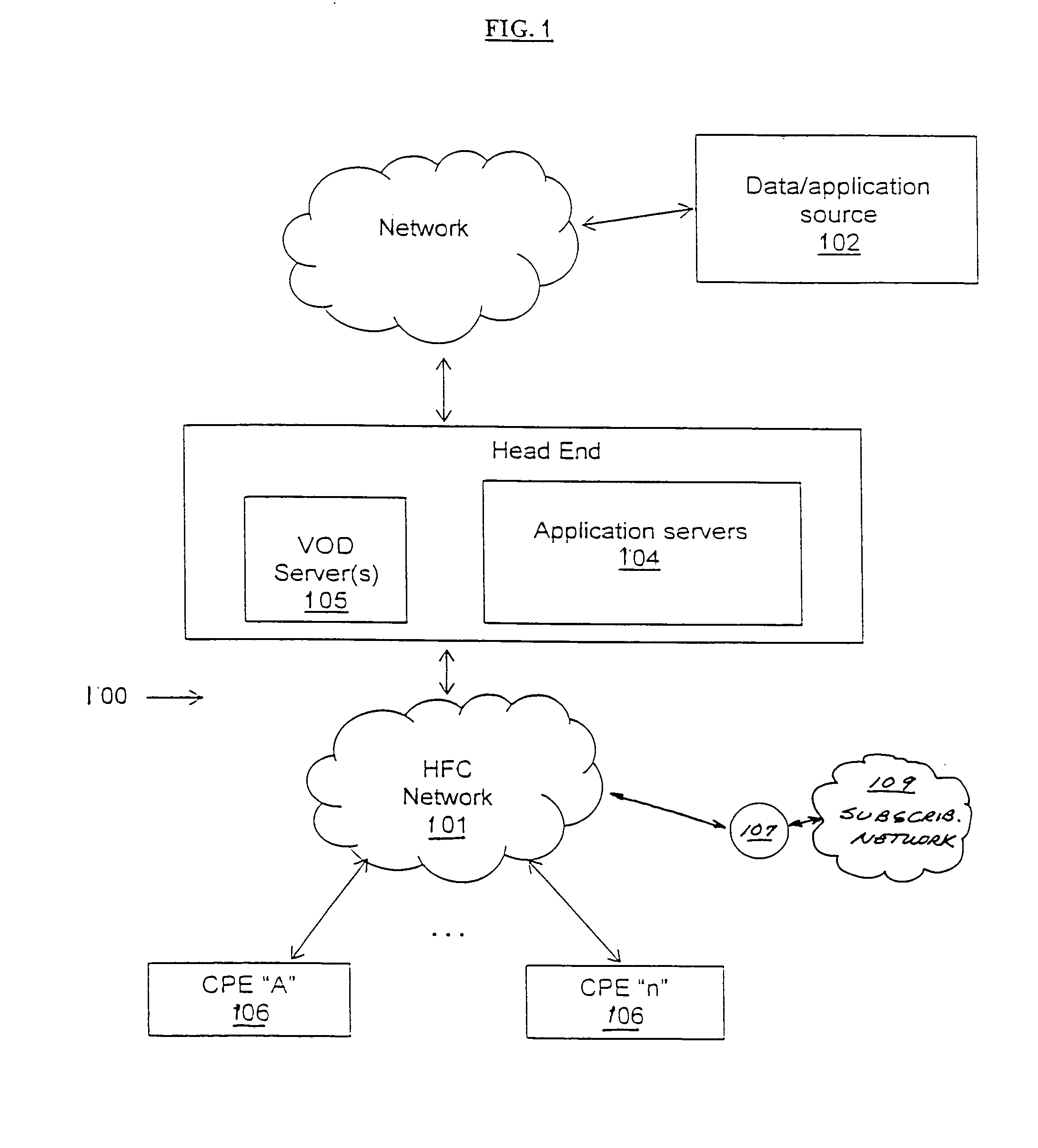
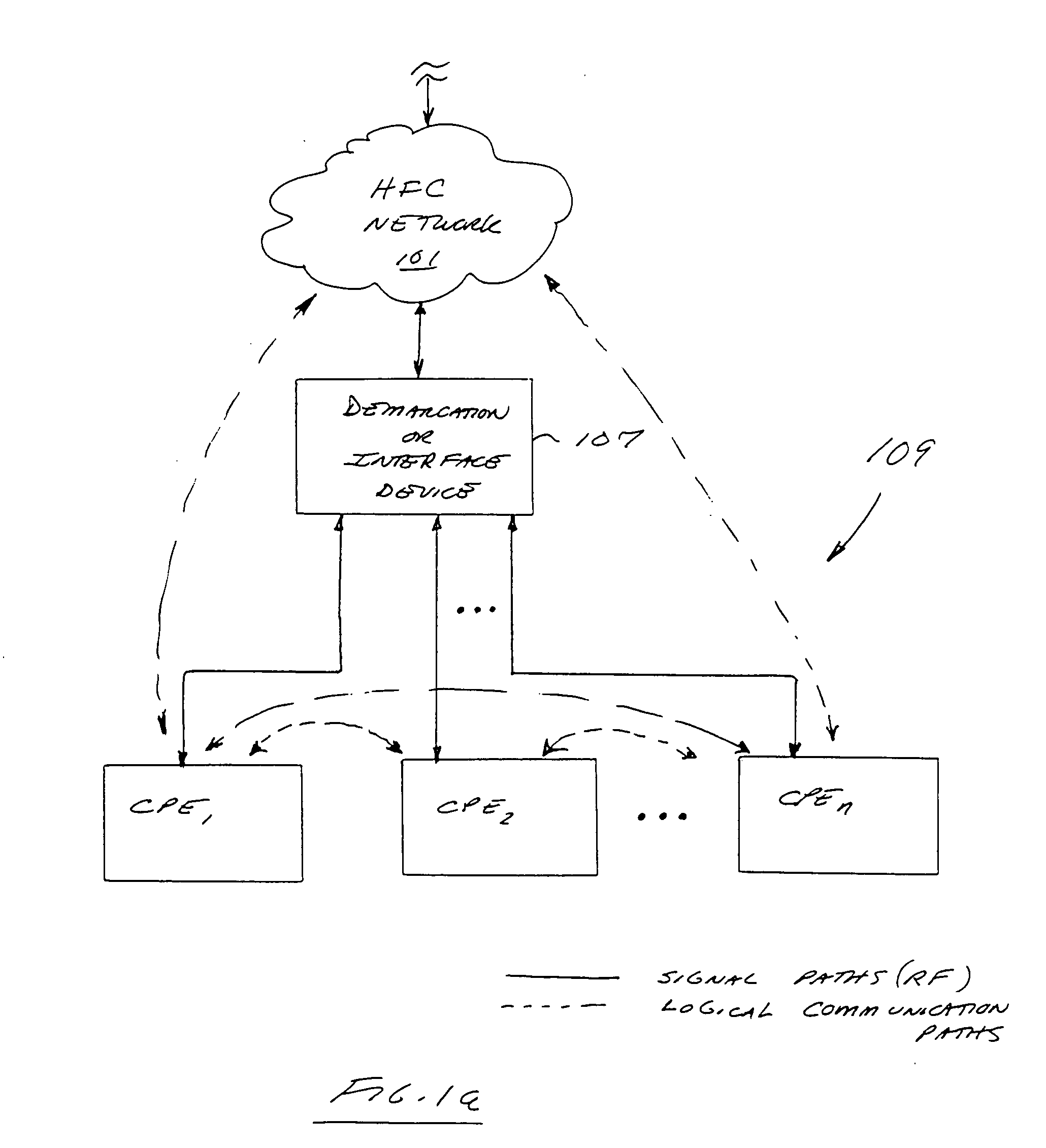
[0055] As used herein, the terms “network” and “bearer network” refer generally to any type of telecommunications or data network including, without limitation, hybrid fiber coax (HFC) networks, satellite networks, telephony networks, and data networks (including MANs, WANs, LANs, WLANs, internets, and intranets). Such networks or portions thereof may utilize any one or more different topologies (e.g., ring, bus, star, loop, etc.), transmission media (e.g., wired / RF cable, RF wireless, millimeter wave, optical, etc.) and / or communications or networking protocols (e.g., SONET, DOCSIS, IEEE Std. 802.3, ATM, X.25, Frame Relay, 3GPP, 3GPP2, WAP, SIP, UDP, FTP, RTP / RTCP, H.323, etc.).
[0056] As used herein, the term “head-end” refers generally to a networked system controlled by an operator (e.g., an MSO or multimedia specific operator) that distributes programming to MSO clientele using cl...
PUM
 Abstract
Description
Claims
Application Information