Plasma processing apparatus and cleaning method thereof

a technology of processing apparatus and cleaning method, which is applied in the direction of chemical apparatus and processes, coatings, chemical vapor deposition coatings, etc., can solve the problems of increasing the leak rate of thermally conductive gas between the wafer w and the susceptor, and achieves the effect of preventing an increase in the leak rate of thermally conductive gas, and not getting worsening the rough surfa

Inactive Publication Date: 2006-01-05
TOKYO ELECTRON LTD
View PDF10 Cites 20 Cited by
  • Summary
  • Abstract
  • Description
  • Claims
  • Application Information

AI Technical Summary

Benefits of technology

[0013] Preferably, in the plasma processing apparatus, the object is a circular plate having a diameter of 300 mm, and a distance between the mounting table and the electrode is approximately 35 mm. When a distance between the mounting table and the electrode is set to approximately 35 mm in a plasma processing apparatus for performing a plasma processing on an object which is shaped as a circular plate having a diameter of 300 mm, surface roughness is not getting worsened on an object mounting surface of the mounting table by ions' collision. Therefore, it can definitely prevent an increase in the leak rate of the thermally conductive gas.
[0014] Preferably, in the plasma processing apparatus, the object is a circular plate having a diameter of 200 mm, and a distance between the mounting table and the electrode is approximately 70 mm. When a distance between the mounting table and the electrode is set to approximately 70 mm in a plasma processing apparatus for performing a plasma processing on an object which is shaped as a circular plate having a diameter of 200 mm, the surface roughness is not getting worsened on an object mounting surface of the mounting table by ions' collision. Therefore, it can definitely prevent an increase in the leak rate of the thermally conductive gas.
[0015] In accordance with a second aspect of the present invention, there is provided a cleaning method including the steps of applying a high frequency power to an electrode; setting an electrical state of a mounting table to a floating state; and making a radical produced from a cleaning gas by the applied high frequency power have a contact with the mounting table. When a high frequency power is applied to the electrode, ions and radicals are produced from the cleaning gas near the electrode. Here, if the electrical state of the mounting table is set to a floating state, a self-bias is not induced in the mounting table. Accordingly, the energy of an ion colliding with the mounting table is small, whereby erosion of the mounting table does not happen. On the other hand, a radical made to have a contact with the mounting table reacts chemically with a deposited reaction product to thereby remove it from the top surface of mounting table. Therefore, the reaction products deposited on the mounting table can be removed without an increase in the leak rate of the thermally conductive gas.
[0016] In the cleaning method of the plasma processing apparatus, preferably, the object is a circular plate having a diameter of 300 mm, and a distance between the mounting table and the electrode is approximately 35 mm. When a distance between the mounting table and the electrode is set to approximately 35 mm in a plasma processing apparatus for performing a plasma processing on an object which is shaped as a circular plate having a diameter of 300 mm, the surface roughness is not getting worsened on an object mounting surface of the mounting table by ions' collision. Therefore, it can definitely prevent an increase in the leak rate of the thermally conductive gas.
[0017] In the cleaning method of the plasma processing apparatus, preferably, the object is a circular plate having a diameter of 200 mm, and a distance between the mounting table and the electrode is approximately 70 mm. When a distance between the mounting table and the electrode is set to approximately 70 mm in a plasma processing apparatus for performing a plasma processing on an object which is shaped as a circular plate having a diameter of 200 mm, the surface roughness is not getting worsened on an object mounting surface of the mounting table by ions' collision. Therefore, it can definitely prevent an increase in the leak rate of the thermally conductive gas.

Problems solved by technology

Accordingly, surface roughness becomes worsened on the susceptor 43's surface facing the upper electrode 42, i.e., the surface for mounting the wafer W thereon, and it becomes difficult to seal a thermally conductive gas supplied through the thermally conductive gas supply holes 48 and the thermally conductive gas supply groove, thereby resulting in an increase in a leak rate of a thermally conductive gas between the wafer W and the susceptor 43.

Method used


Image

  • Plasma processing apparatus and cleaning method thereof
  • Plasma processing apparatus and cleaning method thereof
  • Plasma processing apparatus and cleaning method thereof

Examples


embodiment 1

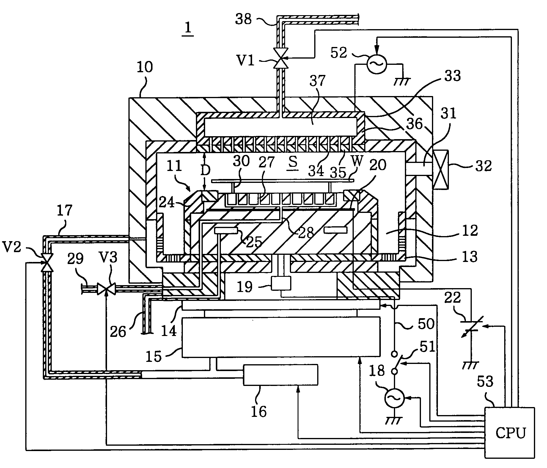
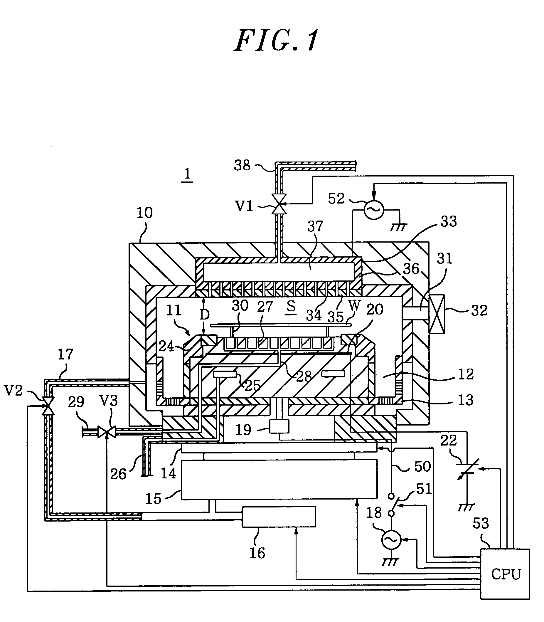
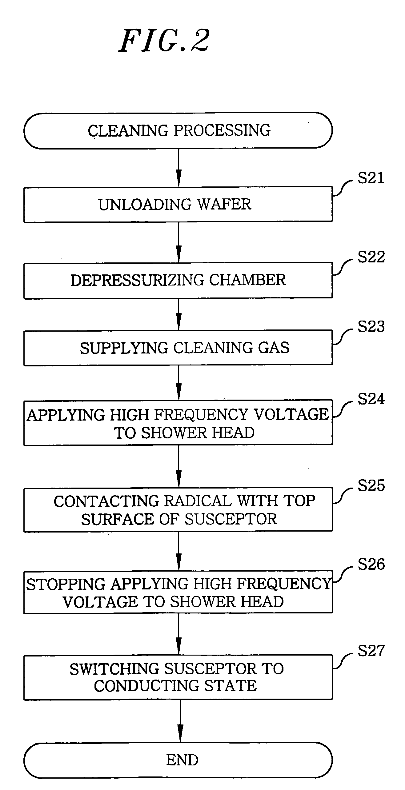
[0054] In the plasma processing apparatus 1, the cleaning processing shown in FIG. 2 was performed under the following conditions.

[0055] Pressure in the chamber 10 : 2.67 Pa

[0056] Kind of cleaning gas : O2 gas

[0057] Supply flow rate of the cleaning gas : 600 SCCM

[0058] High frequency power applied to the shower head 33: 2000 W

[0059] Subsequently, after seasoning, pressure of He gas supplied through the thermally conductive gas supply holes 27 was set to 0.667 kPa, and an etching process was performed on the wafer W. The leak rate of He gas from a gap between the attracting surface and the bottom surface of the wafer W was measured against the total application time (hereinafter, referred to as “total RF time”) of the high frequency power applied to the susceptor 11 and the shower head 33. Then, measurement results are represented by a solid line on a graph of FIG. 3. Further, average surface roughness on the attracting surface was measured at total RF times of O hour, 1300 hour...

embodiment 2

[0060] In the plasma processing apparatus 1, the cleaning processing shown in FIG. 2 was performed under the same conditions as Embodiment 1.

[0061] Subsequently, after seasoning, pressure of He gas supplied through the thermally conductive gas supply holes 27 was set to 3.33 kPa, and an etching process was performed on the wafer W. The leak rate of He gas from a gap between the attracting surface and the bottom surface of the wafer W was measured against the total RF time of the high frequency power applied to the susceptor 11 and the shower head 33. Then, measurement results are represented by a dashed dotted line on the graph of FIG. 3. Further, the average surface roughness on the attracting surface was measured at total RF times of O hour, 1300 hours and 3231 hours, respectively.

embodiment 3

[0062] In the plasma processing apparatus 1, the cleaning processing shown in FIG. 2 was performed under the same conditions as Embodiment 1.

[0063] Subsequently, after seasoning, the pressure of He gas supplied through the thermally conductive gas supply holes 27 was set to 6.67 kPa, and an etching process was performed on the wafer W. The leak rate of He gas from a gap between the attracting surface and the bottom surface of the wafer W was measured against the total RF time of the high frequency power applied to the susceptor 11 and the shower head 33. Then, measurement results are represented by a dashed double-dotted line on the graph of FIG. 3. Further, average surface roughness on the attracting surface was measured at total RF times of O hour, 1300 hours and 3231 hours, respectively.

[0064] In each embodiment, after the cleaning processing shown in FIG. 2 was performed, it was observed by the naked eye that the reaction products deposited on the top surface (attracting surfa...


PUM

PropertyMeasurementUnit
diameteraaaaaaaaaa
diameteraaaaaaaaaa
diameteraaaaaaaaaa

Abstract

A plasma processing apparatus includes a mounting table for mounting thereon an object to be processed, an electrode connected to a high frequency power supply, an electrical state setting unit for setting an electrical state of the mounting table to a conducting state or a floating state, and a controller for controlling the high frequency power supply to apply a high frequency power to the electrode and controlling the electrical state setting unit to set an electrical state of the mounting table to a floating state. Further, a radical produced from a cleaning gas by the applied high frequency power is made to have a contact with the mounting table.

Description

CROSS-REFERENCE TO RELATED APPLICATIONS [0001] This document claims priority to Japanese Patent Application Number 2004-197948, filed Jul. 5, 2004 and U.S. Provisional Application No. 60 / 598,424, filed Aug. 4, 2004, the entire content of which are hereby incorporated by reference.FIELD OF THE INVENTION [0002] The present invention relates to a plasma processing apparatus and a cleaning method thereof; and, more particularly, to a plasma processing apparatus including a mounting table for mounting thereon an object to be processed and a cleaning method thereof. BACKGROUND OF THE INVENTION [0003] Conventionally, a parallel plate type plasma processing apparatus 40 shown in FIG. 4 is used as one of apparatuses for performing a plasma processing such as a film forming process or an etching process on a wafer W serving as an object to be processed. The plasma processing apparatus 40 includes an upper electrode 42 and a susceptor 43, which are disposed in parallel to face each other, havi...

Claims


Application Information

Patent Timeline
Patent Type & Authority Applications(United States)
IPC IPC(8): C23F1/00C23C16/00
CPCB08B7/0035H01J37/32862H01J37/32522H01J37/32082
Inventor TANAKA, HIDEAKIKON, YOSHIMITSU
Owner TOKYO ELECTRON LTD
Why Eureka
Try Eureka