Method and apparatus for controlling and adjusting the intensity profile of a laser beam employed in a laser welder for welding polymeric and metallic components

a laser beam and laser welder technology, applied in the direction of mechanical control devices, controlling lamination, process and machine control, etc., can solve the problems of undesirable variation of the properties of the bonded region, and achieve the effect of improving the signal-to-noise ratio of the detected infrared radiation

Inactive Publication Date: 2006-01-05
BOSTON SCI SCIMED INC
View PDF97 Cites 72 Cited by
  • Summary
  • Abstract
  • Description
  • Claims
  • Application Information

AI Technical Summary

Benefits of technology

[0034] In accordance with another aspect of the invention, the signal to noise ratio of the detected infrared radiation is improved by optically modulating and amplifying the infrared radiation and filtering out the radiation which is not modulated.

Problems solved by technology

One problem with the laser welding technique disclosed in the aforementioned patent is that it typically utilizes a predetermined static laser power over a short pulse or multiple pulses.
This can cause the properties of the bonded region to vary undesirably.
While this technique allows the amount of energy provided to the bond site to be dynamically adjusted based on the temperature of the bond region, it suffers from a problem that arises because the catheter and dilatation balloon are not necessarily formed from the same materials.

Method used


Image

  • Method and apparatus for controlling and adjusting the intensity profile of a laser beam employed in a laser welder for welding polymeric and metallic components
  • Method and apparatus for controlling and adjusting the intensity profile of a laser beam employed in a laser welder for welding polymeric and metallic components
  • Method and apparatus for controlling and adjusting the intensity profile of a laser beam employed in a laser welder for welding polymeric and metallic components

Examples


Embodiment Construction

[0046] The embodiments of the present invention described below are not intended to be exhaustive or to limit the invention to the precise forms disclosed in the following detailed description. Rather, the embodiments are chosen and described so that others skilled in the art may appreciate and understand the principles and practices of the present invention.

[0047] The present invention is directed to methods and apparatuses for effectively bonding components of polymeric materials together, and in particular for bonding components of medical devices, such as catheters. Additionally an aspect of the present invention may be used to bond polymeric materials to non-polymeric materials such as metals, for example, stainless steel as well as other non-polymeric materials such as ceramics and glasses. In particular, the present invention can advantageously provide the ability to bond tubular components of polymeric materials together as are usable for making up components of medical cat...


PUM

PropertyMeasurementUnit
wavelengthaaaaaaaaaa
angleaaaaaaaaaa
angleaaaaaaaaaa

Abstract

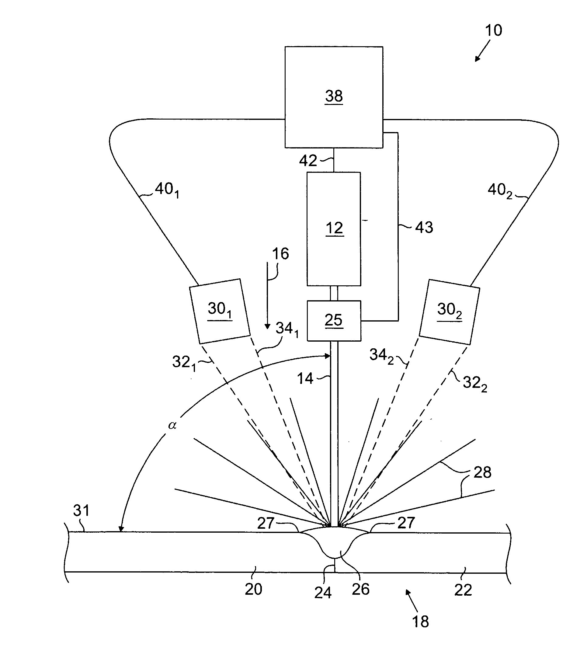
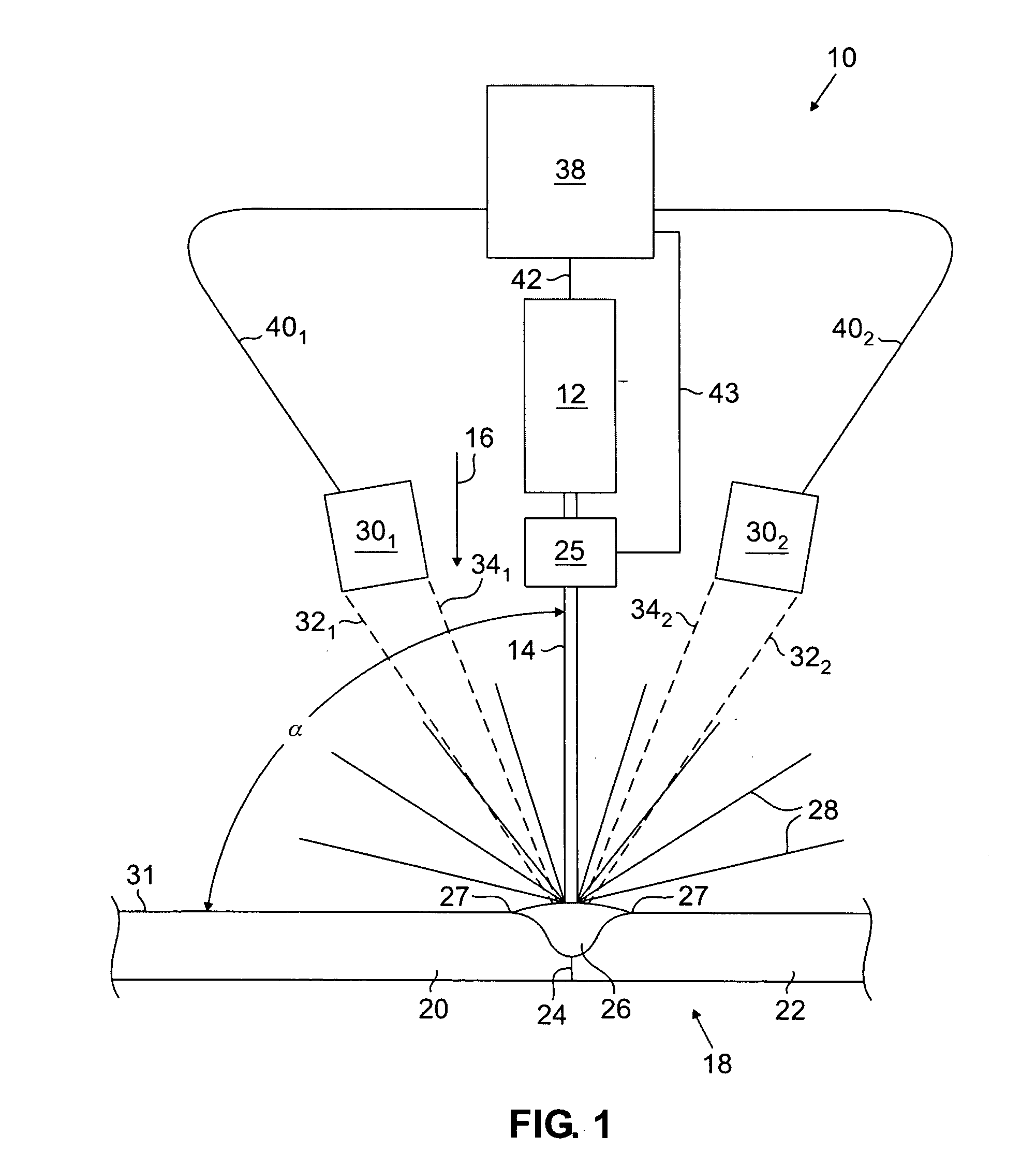
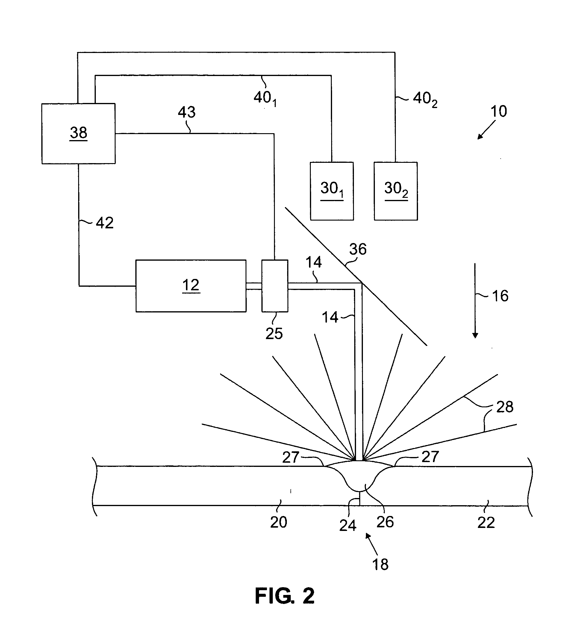
A method and apparatus is provided for forming a fusion bond between two materials such as two components of a catheter. The method begins by forming a bond site by positioning a portion of a first body with respect to a portion of a second body so that a fusion bond site is formed. A laser beam is generated that has an intensity profile across its width. The laser beam is directed onto at least a portion of the first and second bodies within the bond site so that a fusion zone having an increased temperature is formed. After the laser beam is generated, the intensity profile of the laser beam that is directed onto the bond site is controllably adjusted by an optical element such as a dynamically-adjustable beam shaping element

Description

FIELD OF THE INVENTION [0001] The present invention relates to bonding of catheter components, which catheters are employed in medical procedures such as angioplasty and stent delivery procedures, and more particularly to a weld bonding method and apparatus that utilizes laser energy for effectively welding together polymeric components, such as medical catheter components. BACKGROUND OF THE INVENTION [0002] Many types of catheters such as balloon catheters, for example, have been developed for treating problems and diseases of body systems including the vascular, pulmonary, lymphatic, urinary, and other body systems that include one or more body lumens. Such catheters advantageously provide treatment by generally minimally-invasive techniques by permitting manipulation of distal features of such catheters from their proximal ends. These catheters may be made up of many components with properties selectively chosen for specific functions. And as a result, it is generally desirable t...

Claims


Application Information

Patent Timeline
Patent Type & Authority Applications(United States)
IPC IPC(8): B23K26/00B32B37/00
CPCB23K26/03B29L2031/7543B23K26/034B23K26/0643B23K26/073B29C65/1616B29C65/1619B29C66/1142B29C66/43B29C66/5221B29C66/534B29C66/742B29C66/91216B29C66/91221B29K2023/065B29K2023/083B29K2027/18B29K2067/00B29K2075/00B29K2305/12B29L2031/7542B23K26/032B29C66/961B29C66/301B29C66/836B29C65/1629B29C65/1638B29C65/1654B29C65/1674B29C66/91411B29C66/91443B29C66/91641B29C66/962B29L2022/022B29C66/71B29C66/73116B29C66/73132B29C66/73921B29K2077/00B29K2071/00B29K2067/006B29K2067/003B29K2033/08B29K2025/04B29K2023/0633B29K2023/0625B29K2021/003
Inventor WEBER, JANHOLMAN, THOMAS J.
Owner BOSTON SCI SCIMED INC
Why Eureka
Try Eureka