Array oscillator and polyphase clock generator

a clock generator and oscillator technology, applied in the direction of pulse automatic control, pulse generation by logic circuits, pulse techniques, etc., can solve the problems of limited phase resolution, limited design, and uneven phase distribution, so as to improve the timing accuracy of the clock, reduce jitter, and high speed

Inactive Publication Date: 2006-01-05
ACUID +1
View PDF1 Cites 183 Cited by
  • Summary
  • Abstract
  • Description
  • Claims
  • Application Information

AI Technical Summary

Benefits of technology

[0054] It is therefore a primary object of the present invention to provide a polyphase clock generator which can operate at very high speed.
[0055] It is another primary object of the present invention to reduce the jitter in the poly phase clock over the prior art.
[0056] It is another primary object of the present invention to improve the timing accuracy of the clock.

Problems solved by technology

The drawback of this approach is that the phase resolution is limited to the delay through a single stage.
However the distribution of the phases tends to be uneven because the delay through the gain stage or inverting stage is usually much larger than the spacing between the taps on the delay chain.
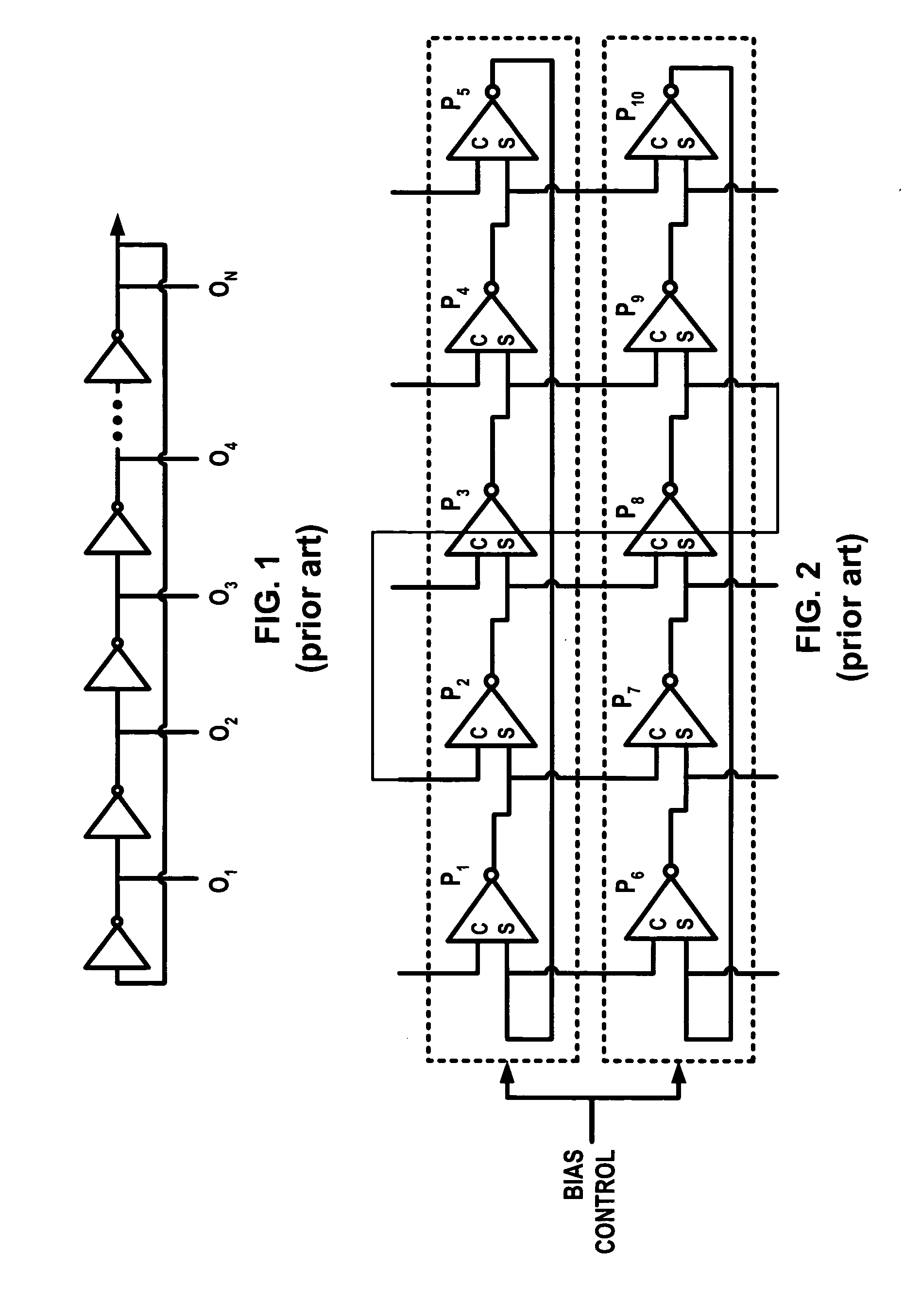
Multiple ring oscillators or registers can be used to generate a poly-phase clock, such as in U.S. Pat. No. 5,268,656, and U.S. Pat. No. 5,347,234, but these designs are limited to lower frequencies than are considered here and the phase relationship tends to be unstable.
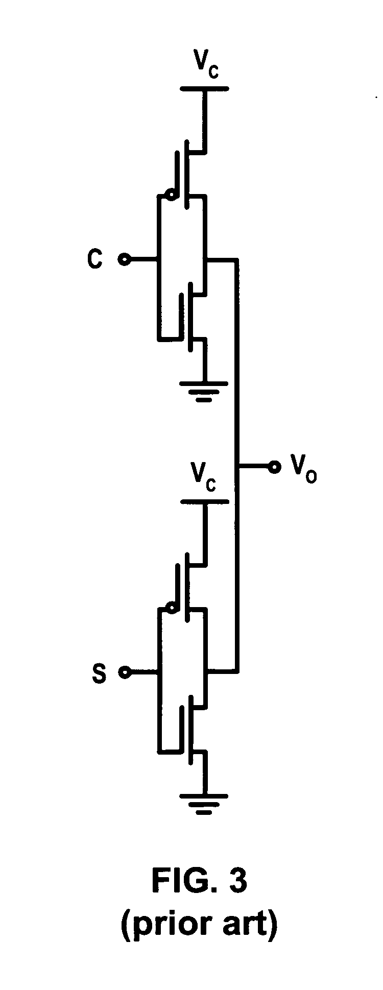
It is noted that the buffers in the implementation described in U.S. Pat. No. 5,426,398 suffer from speed limits due to the use of P-type pull up transistors and common biasing.
Both these patents contain discrepancies between text and figures, which makes it very hard to understand what is being described, and none of the circuits described in the patent were found by the inventors to work when simulated with SPICE.
There are three problems with these two patents which must be considered before their utility can be understood.
There appears to be no way of connecting an array of identical stages such that they operate in fundamental mode.
This means the performance of any array oscillator of the form described in U.S. Pat. No. 5,717,362 and U.S. Pat. No. 5,475,344, is unpredictable, both in the frequency at which it operates and the phases it generates.
The first issue is to sort out what the patent is actually describing, and foremost in this is determining in what mode the rings operate.
This means that unless the array operates properly as a series of fundamental mode rings, it is very difficult to predict what the output frequency will be at any moment in time.
It appears that it is not possible to achieve this for any array described in these two patents.
This means the array does not work in fundamental mode as purported.
Discrepancies and missing labels such as this on this key Fig. do not aid the understanding of these two patents.
It is not possible to arrange the feedback in any of the array oscillators drawn in these two patents, U.S. Pat. No. 5,717,362 and U.S. Pat. No. 5,475,344, to create a constant phase relationship between the S and C inputs of each stage with the oscillators operating in their fundamental mode.
Without such a constant phase relationship, these earlier inventions simply fail to work as described.
There is no way to connect the feedback within an array of identical stages such that each stage has the same relative phase shift on its inputs, if the maximum phase shift within the array is 180 degrees.
With an uneven phase relationships on the C and S inputs of the stages, the array oscillator either fails to work at all or its fundamental mode operate with large amounts of phase noise or jitter, depending on the exact feedback used.
This is not the fundamental mode, and there is the risk this mode will die out sooner or later due to noise, and there is a difficulty in predicting the frequency at which the oscillators operate.
That is, it does not have any benefit at all over a single ring oscillator and operates in the same manner as the prior art but more slowly.
Unfortunately, without any of the Figures in these two patents showing the full feedback scheme, and the inconsistency between text and Figures, much interpretation is needed.
After performing such an exhaustive set of implementations, it transpires that very few feedback schemes work in any mode.
For even these improved schemes, the results are unpredictable.
Due to the unstable nature of non-fundamental mode operation, changes to the loading of the stages, such as by the circuits they drives, can change their operating mode, but in no instance has this mode been observed to be the fundamental mode.
The conclusion of an analysis of U.S. Pat. No. 5,717,362 and U.S. Pat. No. 5,475,344 is that the oscillators do not operate as described, none of the example embodiments operate correctly, and oscillators of the general type described by these patents are both slow and unpredictable.
The mode in which these oscillators operate, may cause them to be slow to start up.
In attempting to make the array oscillate on its own, as in their FIG. 21, the same problems of multi-modal operation are encountered.
A limitation with all of the prior art is that they are limited in their speed by the use of single ended inverters, or differential buffer stages based on using a well known buffer circuit, shown in FIG. 10, which reproduces FIG. 16 from U.S. Pat. Nos. 5,475,344 and 5,717,362.
The use of resistors, such as poly-silicon resistors, is not practical because the parasitic capacitance these carry is even higher than for the P type MOSFETs.

Method used


Image

  • Array oscillator and polyphase clock generator
  • Array oscillator and polyphase clock generator
  • Array oscillator and polyphase clock generator

Examples


Embodiment Construction

[0134] The invention will now be described in detail without limitation to the generality of the present invention with the aid of example embodiments and accompanying drawings.

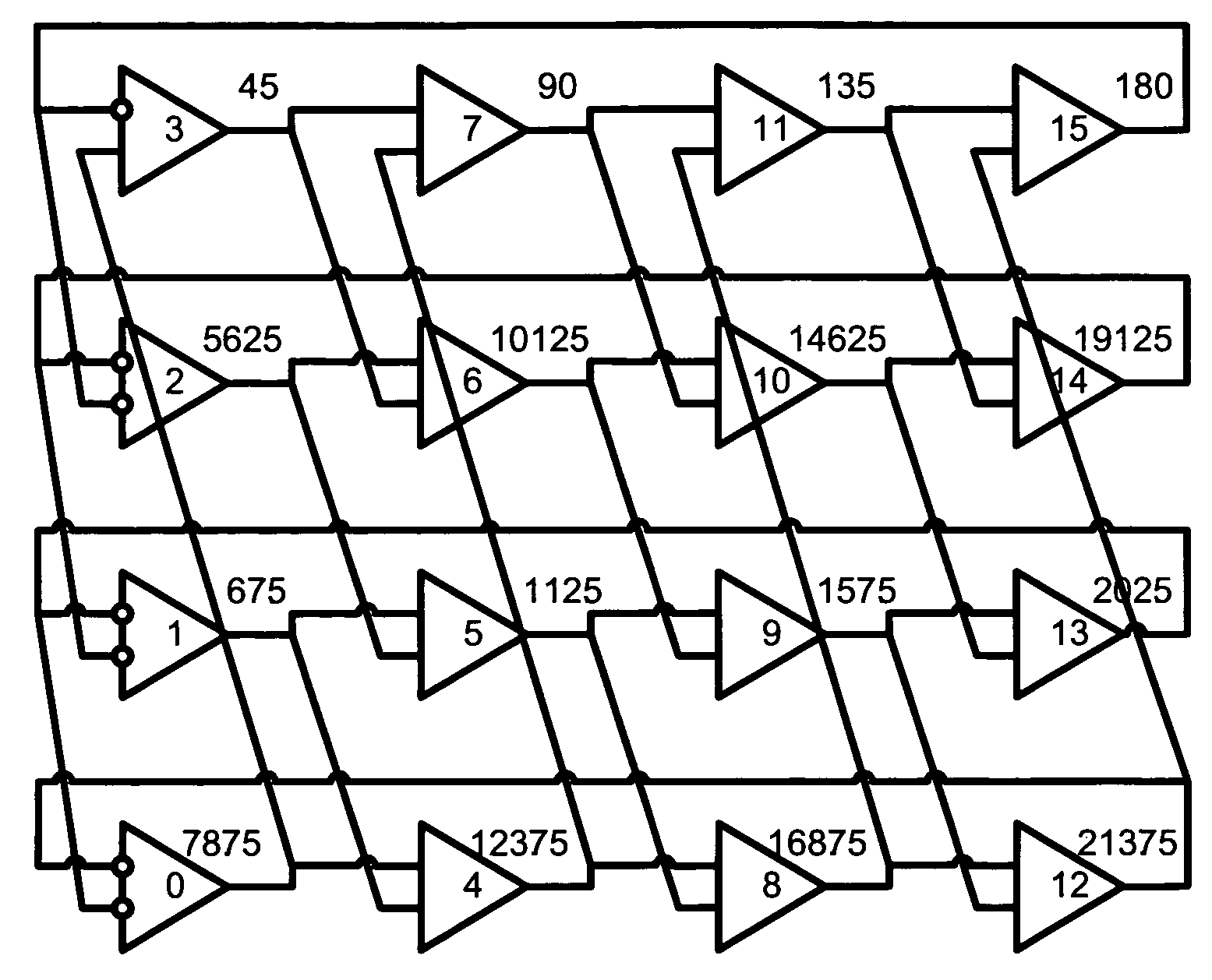
[0135] Consider FIG. 11, which is an example of an array of inter-coupled ring oscillators according to the present invention. Each ring oscillator comprises an inverting stage and a series of non-inverting stages. For example, a first ring oscillator comprises inverting stage P0 and a series of non-inverting stages P4, P8, P12 and the second oscillator comprises an inverting stage P1 and non-inverting stages P5, P9, P13). In this embodiment, each stage should be assumed to be the same and formed from a differential inverter. To create the non-inverting stages, the two inverting inputs to the stage are swapped. Each inversion of the signal is represented by a circle with white inside, as is the common practice for engineering drawings.

[0136] Preferably, the suitable buffer stages are as disclosed by the inv...


PUM


Abstract

The present invention relates generally to array oscillator circuits for use as phase delay generators. More particularly, the present invention relates to a novel array oscillator for providing a plurality of phases which have stable phase relationships. The present invention is particularly applicable to the generation of poly-phase clocks for receivers of very high speed interfaces which employ an over-sampling technique, or multiplexing, and for high speed logic. The array oscillator according to the invention comprises at least one ring oscillator having a plurality of at least two interconnected buffer stages including at least one, or any integer odd number of inverting stages and a series of non-inverting stages, wherein the buffer stages are formed of N-type MOSFET transistors.

Description

BACKGROUND OF THE INVENTION [0001] 1. Technical Field [0002] The present invention relates generally to array oscillator circuits for providing a plurality of phases which have stable phase relationships. [0003] The present invention is particularly applicable to the generation of poly-phase clocks for receivers of very high speed interfaces which employ an over-sampling technique, or multiplexing, and for high speed logic. [0004] 2. Background of the Invention [0005] Ring oscillators are very well known and have been used for many decades to generate a clock signal. The simplest such oscillator is an inverter with the output fed back to the input. To ensure the oscillation covers sufficient voltage or current swing to represent a logical 0 and 1, a Schmitt oscillator is often used. Thirty years ago, this was often a 7414 TTL device. The oscillation frequency was often set using a low pass RC circuit (series R from 7414 output to input, and capacitor from input to ground). These osc...

Claims


Application Information

Patent Timeline
Patent Type & Authority Applications(United States)
IPC IPC(8): H03K3/03
CPCH03K3/0322H03K5/133H03L2207/06H03L7/0995
Inventor ABROSIMOV, IGOR ANATOLIEVICHDEAS, ALEXANDER ROGER
Owner ACUID
Why Eureka
Try Eureka