Fastener apparatus for roofing and steel building construction

a technology for fasteners and steel buildings, applied in the direction of washers, fastening means, screws, etc., can solve the problems of allowing rust and destroying protective coatings, and achieve the effects of reducing wind buffeting, reducing friction during snow unloading, and reducing friction

Inactive Publication Date: 2006-01-05
DREAM WEAVER
View PDF99 Cites 30 Cited by
  • Summary
  • Abstract
  • Description
  • Claims
  • Application Information

AI Technical Summary

Benefits of technology

[0012] The head of the inventive fastener should have a profile as low as possible to reduce friction during snow unloading. This low profile shape should also have a smooth aerodynamic shape to reduce wind buffeting which causes panel vibration in high wind areas. The design should have a recess under the head to hold the rubber seal. The recess should be as wide and as deep as possible so the seal can expand during application and create a barrier of rubber between the lip of the screw head and the panel or product being fastened. This prevents the lip from scratching the zinc coat or paint from the surface of the product below, therefore causing the protective coating to be destroyed and enabling rust. This barrier of rubber between the lip and the panel being fastened also protect the metal fastener and the metal panel from electrolysis which advances the aging process of both fastener and panel.
[0013] The lip should also have four specific features to it. The first is on the inside of the lip, the top half of which should be a vertical wall to stop the seal from expanding wider and cause it to expand downward against the surface below, but the bottom edge should be rounded to allow the rubber seal to squeeze out from beneath the screw and not be cut or pinched. The second is the bottom edge of the lip, which should not be flat which would create a sharp edge and then could easily scratch protective coatings, but should be rounded to reduce the possibility of scratching the coatings and also to not cut or pinch the rubber seal that is supposed to be escaping the recess. The third is the outside edge of the lip, which should also be rounded so as to not cut the rubber seal that is escaping from the recess, and not to scratch the painted surface should the seal be pinched anyway, but also and foremost for the reason that if the fastener is installed at an angle the outer rim will be the first to make contact and a rounded edge will do less damage to the protective paint or coating on the panel being fastened.
[0014] The fastener may also have a locking teeth design that should be sharpened opposite the direction of application, which allows the fastener to be applied and the teeth to slide in easily without removing any metal. This sharpened angle will expand the rubber seal without damaging it during application. The teeth should extend below the head line to ensure contact with the panel or product being fastened and lock itself down should forces attempt to unscrew the fastener. Next, the thickness and the width of the rubber seal should be in the proper ratio to the depth and width of the recess in the head, working in unison with the locking teeth.
[0015] All of these features act together as a depth gauge to stop the rim of the screw from making contact with the panel being fastened below. First, the thick and wide rubber seal make contact which informs the operator that the head is nearly installed, and for installation to slow down or stop. Second, the locking teeth make contact with the raised cone-shaped deformity in the panel (which is caused by the screw threads penetrating the metal panel) and the teeth dramatically increase resistance and slow the installation. The second dramatic slow down informs the installer that the locking teeth have made contact with the metal panel and the installation is complete. The locking teeth preferably begin below the headline at the threads to ensure contact, but the teeth begin at a near vertical angle and curve wider as they approach the head. This curved V-shave versus a sharp straight line V-shape allows the teeth to slide into the rubber seal and metal panel to spread the seal without damaging it, and to make contact with the metal panel and not remove any metal which will serve as a surface for the locking teeth to bite into.
[0016] It is therefore an object of the present invention to provide a new and improved fastener that can withstand the elements.

Problems solved by technology

This prevents the lip from scratching the zinc coat or paint from the surface of the product below, therefore causing the protective coating to be destroyed and enabling rust.

Method used


Image

  • Fastener apparatus for roofing and steel building construction
  • Fastener apparatus for roofing and steel building construction
  • Fastener apparatus for roofing and steel building construction

Examples


embodiment 100

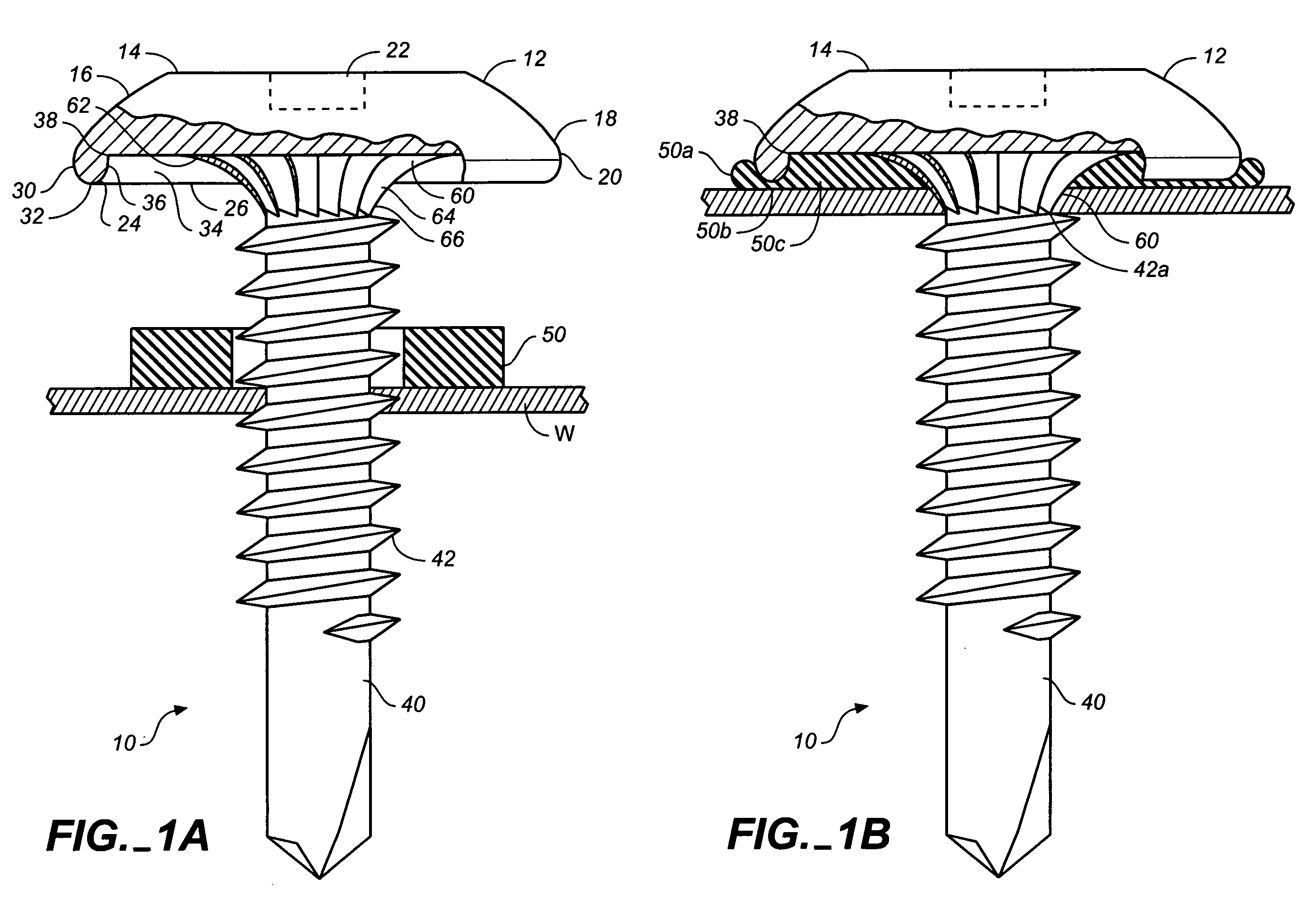
[0065]FIG. 2A is a side elevation view in partial cross-section of an alternate (no locking teeth) embodiment 100 of a fastener apparatus of this invention during installation, while FIG. 2B is a side elevation view in partial cross-section of the fastener 100 as installed. On this design, the shank threads 102 stop below the headline 104 so as to stop the raised metal panel protrusion from riding into the recess 106 and damaging the seal 108. This is a depth gauge 110 which stops the lip 112 from making contact. This upper shank area is also not threaded so the head to shank connection is larger and stronger so as to support the wide head design without the head easily shearing off.

embodiment 200

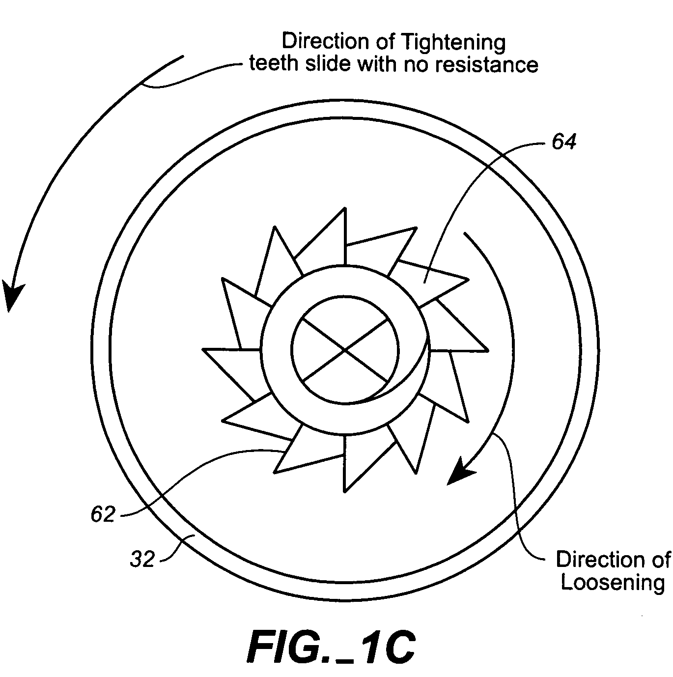
[0066]FIG. 3A is a side elevation view of a self-tightening head embodiment 200 of a fastener apparatus of this invention, while FIG. 3B is a top plan view of the fastener 200 as installed. The head of this particular design works with the snow and ice that is unloading off a rooftop and sliding over the fastener head. The intent is to have a series of raised vertical walls 202 that are sharp at the top 204 and with a backside 206 that slopes down from the top of one vertical wall to the bottom of the next vertical wall. The overall shape is somewhat similar to that of a propeller. The concept has the vertical wall side catching the snow and ice sliding which will apply a turning force in the direction of tightening the fastener. This wall must be limited to prevent snow and ice from over tightening and stripping the fasteners teeth from the substructure.

[0067] The backside in this design is sloped from the top of one vertical catch wall, around the head and down to the bottom of th...

embodiment 400

[0071]FIG. 5 is a side elevation view in partial cross-section of a nail head and elongated thread shank embodiment 400 of a fastener apparatus of this invention during installation. This is a nail design that utilizes many of the features described above. The differences are a nail head 402 which does not require a tool fitting to be punched into it, therefore a standard shank size will remain at its intended strength.

[0072] Elongated threads 404 impart a twisting motion during application that will allow the locking teeth 406 to work similarly to how they work when using a shank with screw threads. The fastener spins as it is applied and locks into place when it tries to unscrew, or in the case of the nail, twist out.

[0073] In order for the head of the inventive fastener designs to remain strong enough to equal ANSI Standards and pass all required UL Testing for use in the field, while incorporating the deep recess and the inset tool fitting which combined will weaken the head, a...


PUM


Abstract

A fastener apparatus includes a frusto-hemispherical head portion having a flat top surface, a curved outer surface, a base portion, and a peripheral edge, with the flat top surface bearing a tool fitting. A downwardly-depending lip portion extends from the head peripheral edge and defines an annular recess in the base, the annular recess having a flat upper surface. The lip has a curved outer edge, a curved lower edge, and an inner edge having a curved lower portion and a vertical upper portion terminating in the annular recess flat upper surface. A shank portion is connected to the base and bears screw threads and a tip. An annular gasket portion is carried on the shank, and has a first uncompressed position contained radially within the annular recess, and a second compressed position extending radially beyond the lip outer edge. As the fastener is installed in a workpiece, the gasket expands to contact the lip inner edge and extend beneath the curved lower edge to form a seal between the fastener head and the workpiece. The fastener may include locking teeth terminating in the head base, adapted to resist loosening of the fastener from the workpiece. The curved outer surface of the fastener may include asymmetric ridges adapted to mechanically engage moving snow or ice to resist loosening of the fastener from the workpiece. The fastener head preferably has a width to height ratio of between 3:1 to 5:1.

Description

CROSS REFERENCE TO RELATED APPLICATIONS [0001] Not applicable. STATEMENT REGARDING FEDERALLY SPONSORED RESEARCH OR DEVELOPMENT [0002] Not applicable. REFERENCE TO A MICROFICHE APPENDIX [0003] Not applicable. TECHNICAL FIELD [0004] The present invention relates generally to construction hardware, and more particularly to an improved fastener apparatus for use in roofing and steel building construction. BACKGROUND INFORMATION AND DISCUSSION OF RELATED ART [0005] Fasteners for use in roofing and steel building construction currently include the ring shank self-sealing nail and the self-sealing hex head. Manufacturers of metal roofing panels recommend that the original self-sealing fasteners be replaced every five years. This replacement is necessary because the rubber seals used on the fasteners are damaged by the sun's UV rays in five years. In addition, snow falls and lands on the rooftop, and when the snow tries to slide off the roof it packs against the high profile heads of the ex...

Claims


Application Information

Patent Timeline
Patent Type & Authority Applications(United States)
IPC IPC(8): F16B43/00
CPCF16B25/10F16B33/004F16B43/001F16B35/06F16B35/048
Inventor CURTIS, DAVID A. W.
Owner DREAM WEAVER
Why Eureka
Try Eureka