Fuel cell

a fuel cell and cell technology, applied in the field of fuel cells, can solve the problems of difficult uniform cooling of electrode surfaces, inability to supply coolant along the entire surface of metal separators, and inability to produce a thin separator using carbon materials, so as to prevent the flow of coolant and prevent the pressure equilibrium in the flow field. , the effect of stable power generation performan

Inactive Publication Date: 2006-01-05
HONDA MOTOR CO LTD
View PDF10 Cites 16 Cited by
  • Summary
  • Abstract
  • Description
  • Claims
  • Application Information

AI Technical Summary

Benefits of technology

[0011] The present invention solves this type of problem, and an object of the present invention is to provide a fuel cell having a simple structure in which a coolant flows in a surface of a separator uniformly, and the desired power generation performance is achieved.
[0015] Therefore, the coolant flows in the surface of the separator uniformly, and cools electrode surfaces uniformly. Thus, the stable power generation performance of the fuel cell can be achieved.
[0018] Therefore, the stagnation of the flow of the coolant due to the pressure equilibrium in the coolant flow field is prevented. Thus, the desired flow rate and the desired flow condition of the coolant in the coolant flow field are achieved. Accordingly, the coolant flows in the separator surface uniformly, and cools the entire electrode surface uniformly. Thus, the stable power generation performance can be achieved.

Problems solved by technology

However, it has been found that it is not possible to produce a thin separator using the carbon material due to factors such as the strength.
Therefore, it is not possible to supply the coolant along the entire surfaces of the metal separators 6a, 6b. Thus, it is difficult to uniformly cool the electrode surfaces, and achieve the stable power generation performance.
Thus, the overall size of the fuel cell stack is large.

Method used


Image

  • Fuel cell
  • Fuel cell
  • Fuel cell

Examples


first embodiment

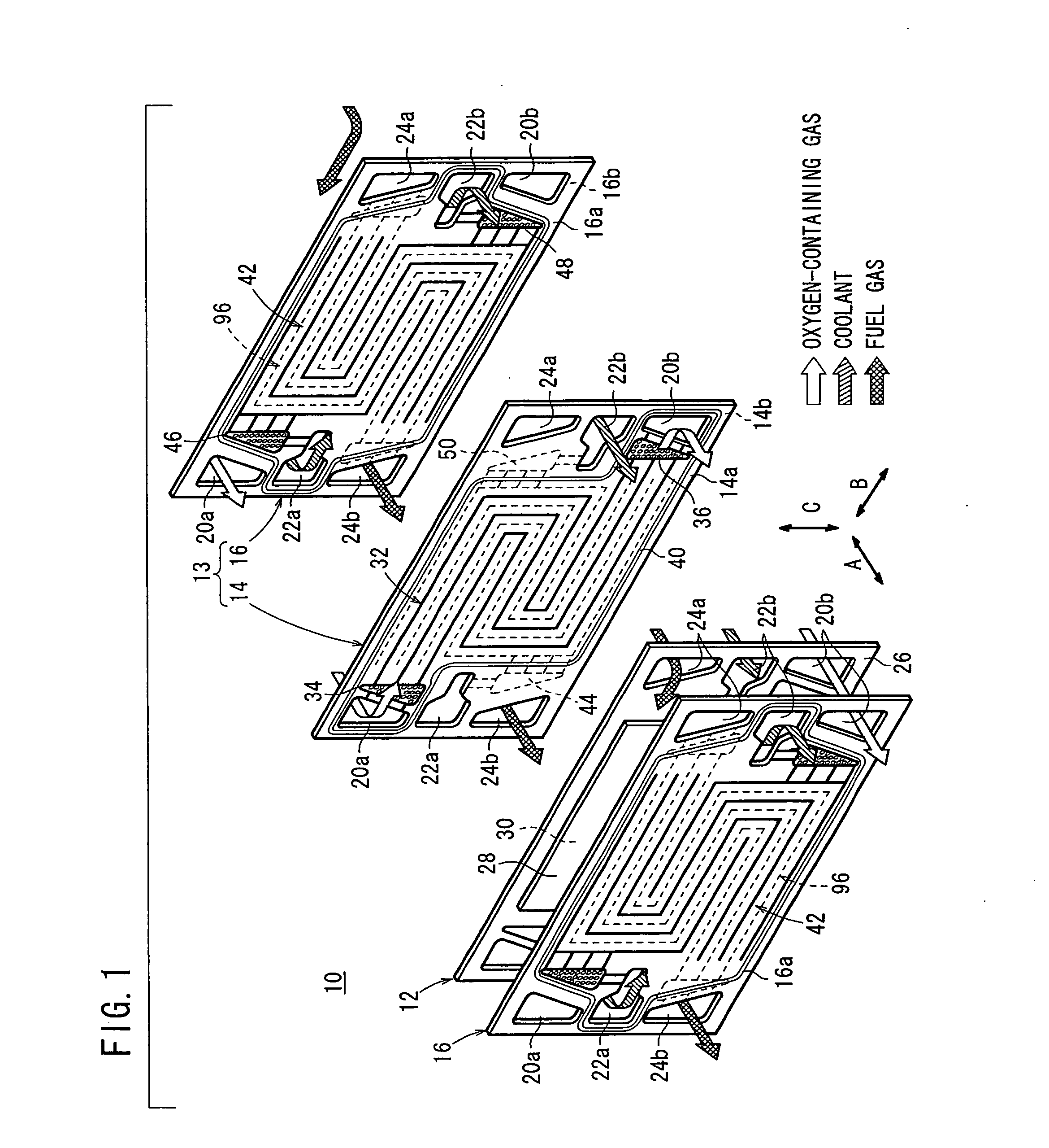
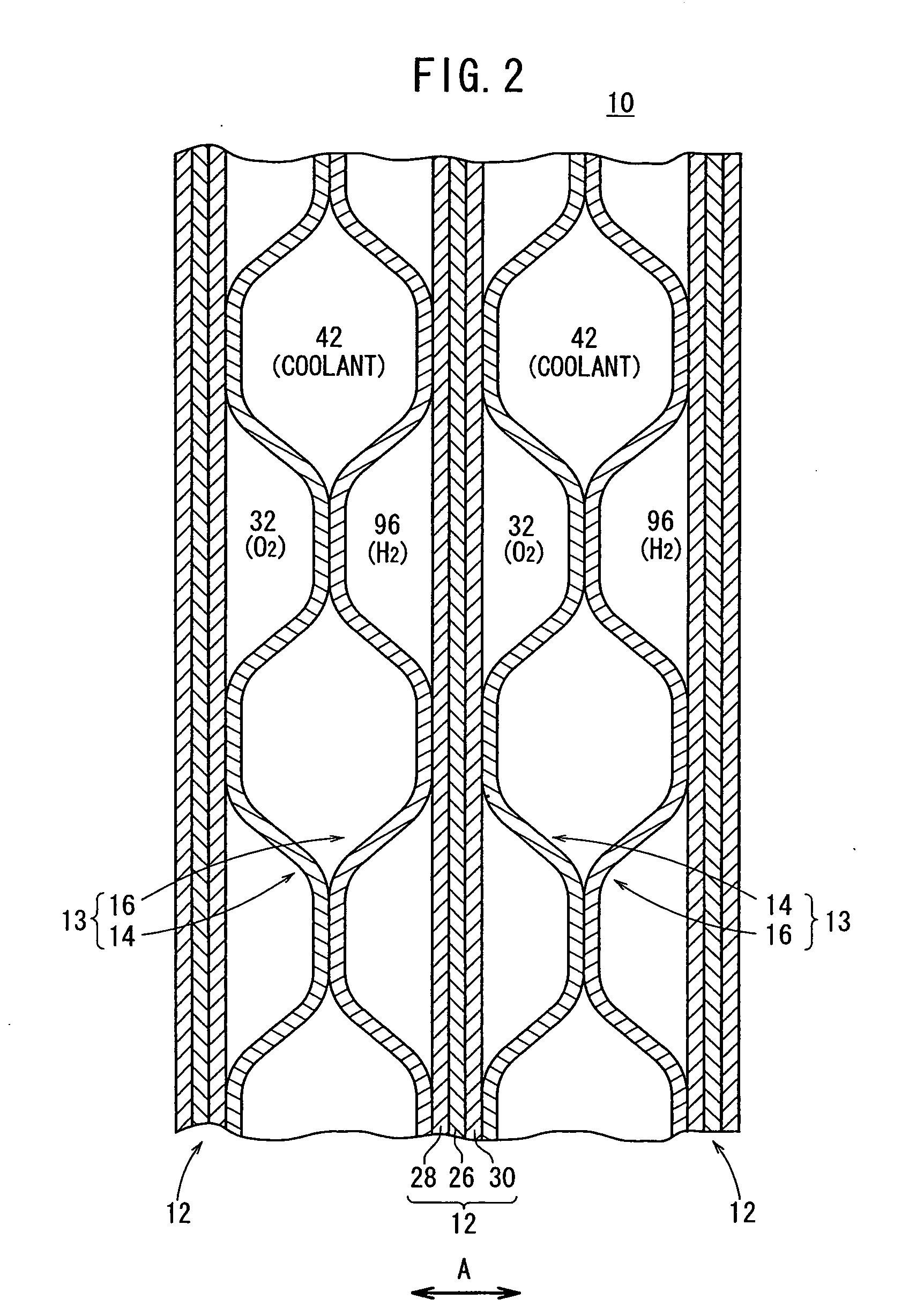
[0047]FIG. 1 is an exploded perspective view showing main components of a fuel cell 10 according to the present invention. FIG. 2 is a cross sectional view showing part of the fuel cell 10.

[0048] The fuel cell 10 is formed by stacking a membrane electrode assembly 12 and separators 13 alternately in a horizontal direction. Each of the separators 13 includes first and second horizontally long rectangular metal plates 14, 16 which are stacked together.

[0049] As shown in FIG. 1, at one end of the fuel cell 10 in a direction indicated by an arrow B, an oxygen-containing gas supply passage 20a for supplying an oxidizing gas such as an oxygen-containing gas, a coolant supply passage 22a for supplying a coolant, and a fuel gas discharge passage 24b for discharging a fuel gas such as a hydrogen-containing gas are arranged vertically in a direction indicated by an arrow C. The oxygen-containing gas supply passage 20a, the coolant supply passage 22a, and the fuel gas discharge passage 24b ex...

second embodiment

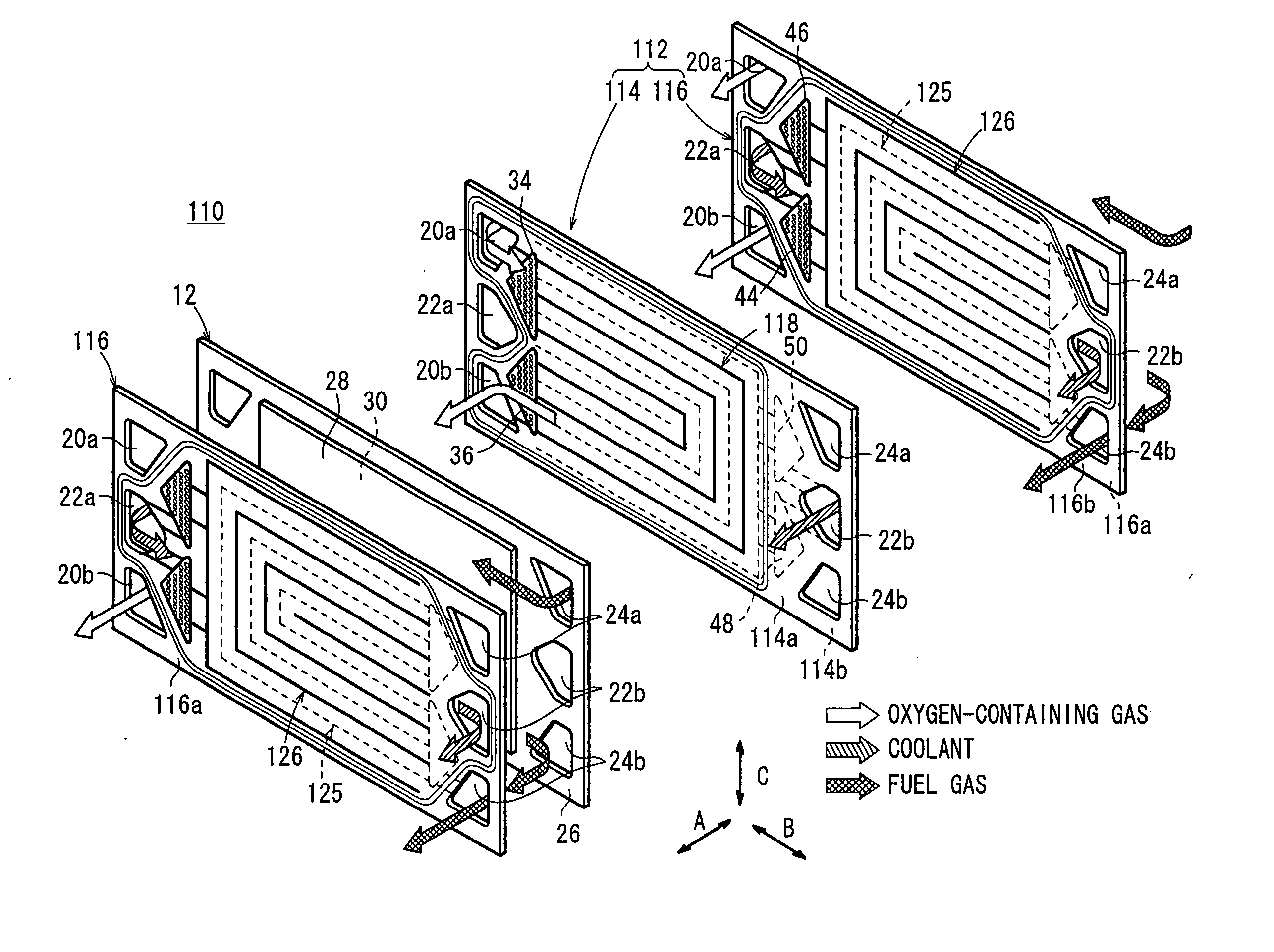
[0092] In the second embodiment, the first metal plate 114 has an oxygen-containing gas flow field 118 on the surface 114a. In the oxygen-containing gas flow field 118, the inlet buffer 34 and the outlet buffer 36 are connected through the oxygen-containing gas flow grooves 124a through 124c each curved in a substantially U-shape. The second metal plate 116 has the fuel gas flow field 125 on the surface 116a. In the fuel gas flow field 125, the inlet buffer 98 and the outlet buffer 100 are connected by the fuel gas flow grooves 131a through 131c each curved in a substantially U-shape.

[0093] In this manner, even though the shape of the grooves for the coolant on the surface 114b of the first metal plate 114 and the shape of the grooves for the coolant on the surface 116b of the second metal plate 116 are constrained, the coolant flow field 126 is formed between the first metal plate 114 and the second metal plate 116 such that the grooves on the first metal plate 114 and the grooves ...

third embodiment

[0095]FIG. 14 is a front view showing a first metal plate 160 of a fuel cell according to the present invention. The first metal plate 160 has an oxygen-containing gas flow field 162 on its surface 160a facing the cathode 30. The oxygen-containing gas flow field 162 is connected to the oxygen-containing gas supply passage 20a and the oxygen-containing gas discharge passage 20b. The oxygen-containing gas flow field 162 includes three oxygen-containing gas flow grooves 164a through 164c connected between the inlet buffer 34 and the outlet buffer 36. The oxygen-containing gas flow grooves 164a through 164c extend in a serpentine pattern for allowing the oxygen-containing gas to flow back and forth in the direction indicated by the arrow B, and flow in the direction indicated by the arrow C. Each of the oxygen-containing gas flow grooves 164a through 164c have four turn regions and five straight regions extending in the direction indicated by the arrow B.

[0096]FIG. 15 is a front view sh...


PUM

PropertyMeasurementUnit
rectangular shapeaaaaaaaaaa
chemicalaaaaaaaaaa
DC electrical energyaaaaaaaaaa

Abstract

A separator comprises a first and second metal plates laid over each other. A cooling medium flow passage is integrally provided between the first and second metal plates. The cooling medium flow passage has inlet buffer portions communicating with a cooling medium inlet communication hole, outlet buffer portions communicating with a cooling medium outlet communication hole, and linear flow passage grooves linearly extending in the direction of arrow B and that of arrow C.

Description

TECHNICAL FIELD [0001] The present invention relates to a fuel cell formed by alternatively stacking an electrolyte electrode assembly and separators. The electrolyte electrode assembly includes an anode, a cathode, and an electrolyte interposed between the anode and the cathode. BACKGROUND ART [0002] For example, a solid polymer fuel cell employs a polymer ion exchange membrane as a solid polymer electrolyte membrane. The solid polymer electrolyte membrane is interposed between an anode and a cathode to form a membrane electrode assembly. Each of the anode and the cathode is made of electrode catalyst and porous carbon. The membrane electrode assembly is sandwiched between separators (bipolar plates) to form the fuel cell. In use, generally, a predetermined number of the fuel cells are stacked together to form a fuel cell stack. [0003] In the fuel cell, a fuel gas (reactant gas) such as a gas chiefly containing hydrogen (hereinafter also referred to as the hydrogen-containing gas) ...

Claims


Application Information

Patent Timeline
Patent Type & Authority Applications(United States)
IPC IPC(8): H01M8/04H01M8/02H01M8/24H01M8/10
CPCH01M8/0247H01M8/0258H01M8/0263H01M8/0267Y02E60/50H01M8/04089H01M8/1002H01M8/241H01M8/04029H01M8/1007H01M8/2483H01M8/2457
Inventor SUGIURA, SEIJIGOTO, SHUHEIMOURI, MASAHIRO
Owner HONDA MOTOR CO LTD
Why Eureka
Try Eureka