
Portable radio terminal, antenna selector control method for use in portable radio terminal, and antenna selector control program

a portable radio terminal and control method technology, applied in the direction of electromagnetic wave modulation, high-level techniques, modulation, etc., can solve the problems of deteriorating the condition of signal transmission/reception of portable radio terminals, and deteriorating in other situations, so as to reduce current consumption, reduce current consumption, and reduce the effect of current consumption

Inactive Publication Date: 2006-01-05
NEC CORP
View PDF10 Cites 12 Cited by
  • Summary
  • Abstract
  • Description
  • Claims
  • Application Information

AI Technical Summary

Benefits of technology

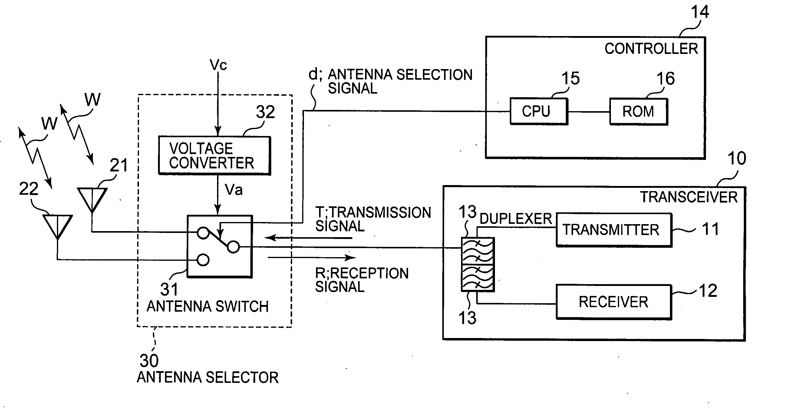
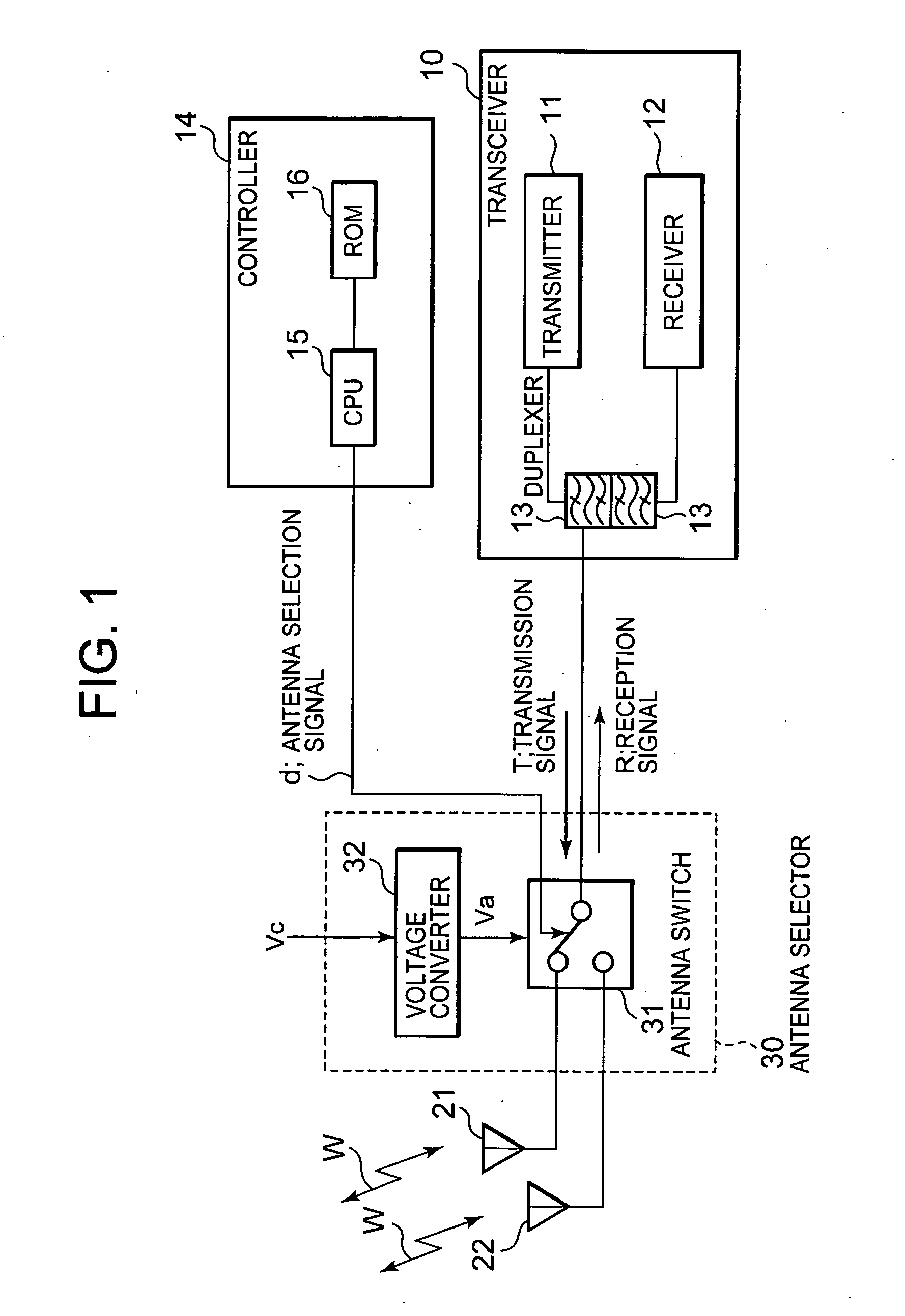
[0009] An object of the present invention is to provide improved control method of switching, of an antenna switch in a portable radio terminal having two or more antennas.
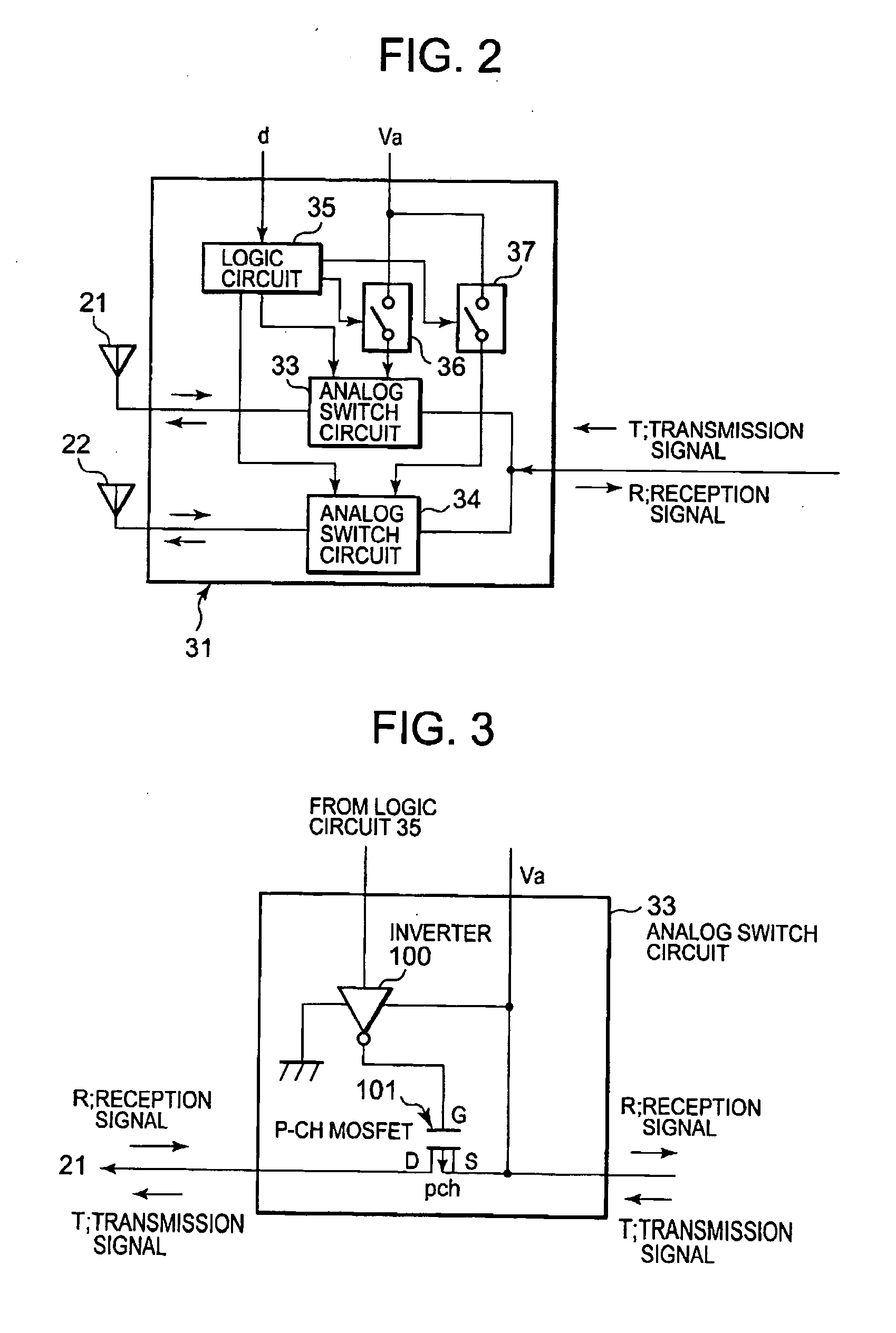
[0010] Another object of the present invention is to improve IMD characteristics of an analog switch circuit in an antenna switch of a portable radio terminal having two or more antennas.
[0011] Still another object of the invention is to reduce the restriction in designing a portable radio terminal by improving the IMD characteristics of an analog switch circuit.
[0012] A further object of the invention is to improve the IMD characteristics of a portable radio terminal while reducing its power consumption.
[0014] According to a configuration of the present invention, a voltage converter controller controls a voltage converter to cause it to operate / halt on the basis of the power level of a transmission signal generated by a transmitter. A predetermined output voltage is applied to an analog switch circuit when the voltage converter is operating, and a power-supply voltage is applied to the analog switch circuit when the voltage converter is halted. This procedure reduces current consumption in the analog switch circuit. Reducing the current consumption lengthens the time during which the portable radio terminal operates. The voltage converter controller provides control so that the voltage converter operates and the predetermined output voltage is applied to the analog switch circuit when the power of the transmission signal generated by the transmitter is equal to or greater than a predetermined threshold, and so that the voltage converter halts and the power-supply voltage is applied to the analog switch circuit in place of the predetermined output voltage when the power of the transmission signal is smaller than the threshold, which reduces the current consumption in the analog switch circuit and lengthens the operating time of the portable radio terminal.
[0015] Also, the voltage converter controller may variably control the output voltage from the voltage converter on the basis of the transmission power value of the transmission signal generated by the transmitter, which further reduces the current consumption in the analog switch circuit and lengthens the operating time of the portable radio terminal.

Problems solved by technology

This may deteriorate the condition of signal transmission / reception of the portable radio terminal.
Even when the radio wave transmission / reception condition is good in one situation, the condition may deteriorate in other situations.
The signal transmission / reception condition of the portable radio terminal may thus deteriorate.
Even when the radio wave transmission / reception condition is good in one situation, the condition may deteriorate in the other situation.
The signal transmission / reception condition of the portable radio terminal may thus deteriorate.
This imposes restrictions on design.

Method used


Image

  • Portable radio terminal, antenna selector control method for use in portable radio terminal, and antenna selector control program
  • Portable radio terminal, antenna selector control method for use in portable radio terminal, and antenna selector control program
  • Portable radio terminal, antenna selector control method for use in portable radio terminal, and antenna selector control program

Examples


first embodiment

[0043]FIG. 4 is a block diagram illustrating the electric configuration of a portable radio terminal according to the present invention.

[0044] As shown in FIG. 4, the portable radio terminal of the embodiment includes a transceiver 40, a detector 44, antennas 51 and 52, an antenna selector 60, and a controller 70. The transceiver 40 includes a transmitter 41, a receiver 42, and a duplexer 43. The transmitter 41 generates a transmission signal T during transmission operation. The receiver 42 receives a reception signal R. The duplexer 43 isolates the transmission signal T and the reception signal R so that they do not interfere with each other. The detector 44, which is formed of a diode for detection, an LPF (Low Pass Filter), etc., detects the transmission signal T and outputs a detection signal “e”. The detection signal contains information about the power of the transmission signal T.

[0045] The antenna selector 60 includes an antenna switch 61, a voltage converter 62, and a semi...

second embodiment

[0069]FIG. 9 is a flow chart showing a control flow performed by the controller 70A of the The control flow will be described referring to the diagram.

[0070] First, the controller 70A measures the transmission power of the transmission signal T on the basis of the detection signal “e” received from the detector (S141). Next, the controller 70A generates the transmission power information p corresponding to the transmission power (S142). The transmission power information p has a digital value. Next, the controller 70A outputs the transmission power information p to the power supply LSI 80 through a signal line (S143).

[0071] The power supply LSI 80 sets the output of the DAC 81 on the basis of the transmission power information p. In order to allow the antenna switch 61 to maintain satisfactory IMD characteristics, the power supply LSI 80 sets the output value of the DAC 81 so that the voltage converter 62 outputs a greater voltage when the transmission power is larger. The DAC 81 ...

third embodiment

[0073]FIG. 10 is a block diagram illustrating the electric configuration of a portable radio terminal according to the present invention, where the same reference characters are assigned to the same elements as those shown in FIG. 4.

[0074] Unlike the portable radio terminal of FIG. 4, this portable radio terminal has no detector 44. Also, the transceiver 40 and the controller 70 of FIG. 4 are replaced by a transceiver 40B and a controller 70B having different configurations. In the transceiver 40B, the transmitter 41 is replaced by a transmitter 41B having a new function. In addition to the functions of the transmitter 41, the transmitter 41B is capable of switching between a normal mode operation and a low power mode operation on the basis of a mode switching signal f from the controller 70B. In a normal mode operation, the transmission power value of the transmission signal T is outputted at a certain fixed value equal to or higher than a given reference value. On the other hand, ...


PUM


Abstract

An antenna selector selects one of the plurality of antennas according to an antenna selection signal. The antenna selector includes a voltage converter and an analog switch circuit. The voltage converter converts a power-supply voltage to a predetermined output voltage higher than the power-supply voltage. The analog switch circuit operates with the predetermined output voltage from the voltage converter or the power-supply voltage being applied thereto. A voltage converter controller controls the voltage converter to operate / halt according to a power level of the transmission signal generated by the transmitter. The predetermined output voltage is applied to the analog switch circuit when the voltage converter is operating and the power-supply voltage is applied to the analog switch circuit when the voltage converter is halted.

Description

BACKGROUND OF THE INVENTION [0001] 1. Field of the Invention [0002] The present invention relates to a portable radio terminal, an antenna selector control method for use in the portable radio terminal, and an antenna selector control program. In particular, the present invention relates to a portable radio terminal in which a transmission signal is sent to an antenna through an analog switch circuit, an analog switch circuit control method for use in the portable radio terminal, and an analog switch circuit control program. [0003] 2. Description of the Related Art [0004] Portable radio terminals include mobile phones conforming to PDC (Personal Digital Cellular), GSM (Global System for Mobile Communications), CDMA (Code Division Multiple Access), PHS (Personal Handy-phone System), etc., PDAs (Personal Digital Assistants) having a radio communication function, notebook personal computers having a radio communication function, and the like. With a portable radio terminal having only ...

Claims


Application Information

Patent Timeline
IPC IPC(8): H04M1/00
CPCH04B7/0802H04B7/0602Y02D30/70
Inventor OGAWA, RYUTARO
Owner NEC CORP
Learn More