Integrated liquid cooling device with immersed electronic components

a technology of electronic components and integrated cooling devices, which is applied in the details of semiconductor/solid-state devices, domestic cooling devices, lighting and heating devices, etc., can solve the problems of no effect on the satisfactory operation of cooling devices, and achieve the effects of increasing the cooling capacity of the integrated cooling device, increasing the surface area, and increasing the surface area

Inactive Publication Date: 2006-01-12
SYMONS ROBERT S
View PDF37 Cites 64 Cited by
  • Summary
  • Abstract
  • Description
  • Claims
  • Application Information

AI Technical Summary

Benefits of technology

[0021] The housing may have any shape, but if a close fitting impeller is desired, the shape of the interior surface of the housing can be generated by rotating about an axis, a line generatrix following any arbitrary path between any two points on that axis. For example, the shape of the housing would be a cylinder if the generatrix rotated about the axis were formed of three straight-line segments that form a rectangle with the axis as the fourth side. The generatrix of a hat shaped enclosure would have five joined straight-line segments between the points on the axis. A curved line-segment would generate a spherical or domed surface. Additionally, the line generatrix may include at least one feature that generates at least one ridge on the resulting interior surface of the housing. Such a feature yields increased surface area as compared with a non-ridged housing. The ridge may be oriented with its highest portion extending into the interior of the housing, or, it may be oriented with its highest portion extending into the wall of the housing (such that a groove is created in the wall of the housing) This increased surface area results in increased cooling capacity of the integrated cooling device. In one preferred embodiment in which high-velocity coolant flow would occur over the largest possible interior surface, the motor and impeller are concentric with and closely fit the housing. Alternatively, the impeller and motor could be located so they provide the highest velocity coolant liquid flow to only that area of the housing where the greatest heat transfer is needed (e.g., near the component to be cooled). Thus, a small motor could provide local high-velocity flow.
[0022] The housing may be completely filled or almost completely filled with a cooling liquid. If the housing is completely filled with liquid, a bellows, flexible diaphragm, or other flexible element must be provided in the housing to allow for thermal expansion of the cooling liquid. On the other hand, if a small volume filled with a compressible gas is provided w

Problems solved by technology

On the other hand, if a small volume filled with a compressible gas is provided within

Method used


Image

  • Integrated liquid cooling device with immersed electronic components
  • Integrated liquid cooling device with immersed electronic components
  • Integrated liquid cooling device with immersed electronic components

Examples


Embodiment Construction

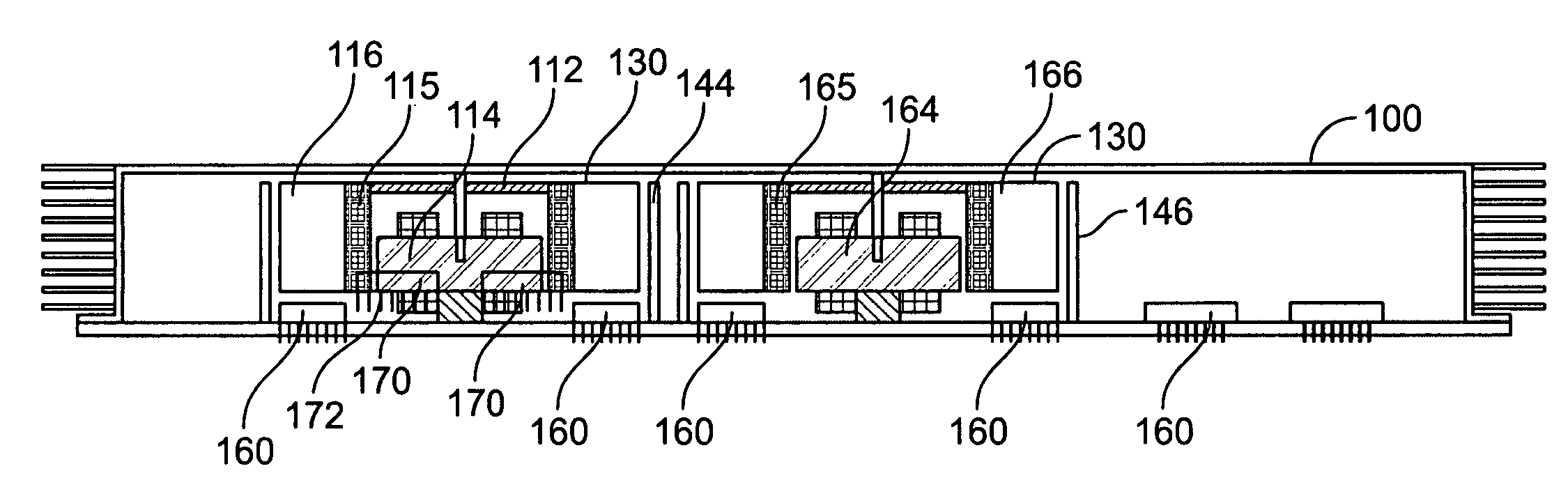
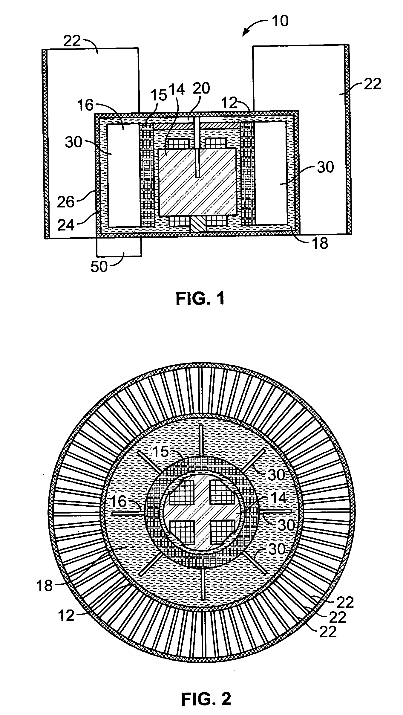
[0034] The present invention provides an apparatus for cooling an electronic component with an integrated cooling device that overcomes the limitations of the prior art. In the detailed description that follows, like numerals are used to denote like elements appearing in one or more of the figures.

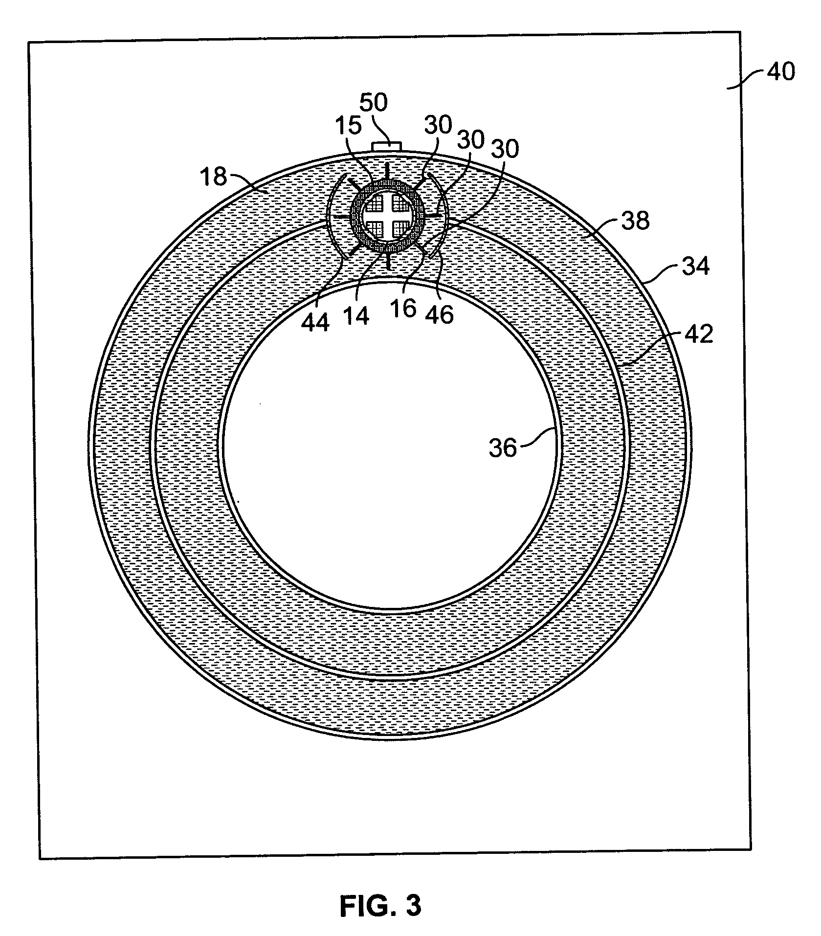
[0035] Referring to FIG. 1, an embodiment of the integrated cooling device 10 of the present invention is depicted in a cross-sectional side view. The integrated cooling device 10 is comprised of a housing 12, a motor stator further comprising pole-pieces and windings 14, a cylindrical permanent magnet rotor 15, an impeller 16, cooling liquid 18, and cooling surfaces 22. The housing 12 of the integrated cooling device 10 has inside surfaces 24 and outside surfaces 26. FIG. 1 depicts the housing 12 as a right circular cylinder, although it should be appreciated that multiple geometries of housings are contemplated within the scope of the present invention. For example, hat-shaped, spherica...


PUM


Abstract

An integrated liquid cooling device for electronic components addresses the need for efficient cooling created by ever increasing power densities of electronic components. The integrated liquid cooling device has a housing enclosing the electronic component, cooling liquid contained in the housing, a motor immersed in the cooling liquid and mounted to the housing, an impeller driven by the motor, and cooling surfaces on the exterior of the housing. The motor driven impeller creates a turbulent flow in the cooling liquid and a high velocity liquid flow over the electronic component, which rapidly transfers heat from the electronic component and distributes it throughout the interior of the housing. The cooling surfaces on the exterior of the housing dissipate this heat, either by free or forced convection, into the surrounding environment. Alternately, the integrated liquid cooling device may distribute this heat energy over an equipment case by circulating cooling liquid through a baffled enclosure that provides high velocity cooling liquid flow near the heat generating electronic component. Additional cooling capacity can be gained with the described integrated liquid cooling device by selecting a cooling liquid whose boiling point is near the operating temperature of the electronic component.

Description

RELATED APPLICATION INFORMATION [0001] This application claims priority under 35 U.S.C. § 120 as a continuation-in-part of U.S. patent application Ser. No. 10 / 888,101, filed Jul. 9, 2004.BACKGROUND OF THE INVENTION [0002] 1. Field of the Invention [0003] The present invention relates to an apparatus and method for cooling electronic components, and more particularly, an integrated cooling device for use with electronic components. [0004] 2. Description of Related Art [0005] Machines and devices that change energy from one form (chemical, mechanical, thermal, or electrical) to another are rarely 100% efficient. Likewise, devices that change or modulate electrical energy in one form to electrical energy in another form are rarely 100% efficient. For example, a transistor, integrated circuit or a microprocessor may change direct current into alternating current or into pulses on many outputs that signify numerical data. Where direct current is changed into alternating current, only par...

Claims


Application Information

Patent Timeline
IPC IPC(8): F24H3/02H05K7/20F28F25/10
CPCH01L23/473H01L2924/09701F28F2250/08H01L2924/0002H01L2924/00
Inventor SYMONS, ROBERT S.
Owner SYMONS ROBERT S
Why Eureka
Try Eureka