Eureka AIR delivers breakthrough ideas for toughest innovation challenges, trusted by R&D personnel around the world.

Device for carrying out a plasma-assisted process

a technology of plasma-assisted process and device, which is applied in the direction of chemical vapor deposition coating, electrical equipment, coating, etc., can solve the problems of high unbalanced magnetron and inability to fully confine electrons

Inactive Publication Date: 2006-01-12
TETRA LAVAL HLDG & FINANCE SA
View PDF2 Cites 7 Cited by
  • Summary
  • Abstract
  • Description
  • Claims
  • Application Information

AI Technical Summary

Benefits of technology

[0007] The object of the invention is to improve the above named devices applicable for plasma enhanced processes, in particular for plasma enhanced chemical vapour deposition but also for e.g. plasma etching or plasma processes for changing the wetability or adhesion characteristics of a surface and belonging to the type being based on a magnetron. The improvement is to regard in particular process efficiency. For a deposition process deposition rate and deposition quality are to be improved.
[0010] Visual observation of a plasma maintained between an unbalanced magnetron with a flat rectangular face (observation parallel to the longer side of the magnetron face) and a surface to be treated and arranged substantially parallel to the magnetron face shows the named tunnels as quite clearly distinguishable darker areas within the plasma, which outside of the tunnels appears brighter. The above discussed setting of the distance between the magnetron face and the substrate to be dependent on the characteristics of the magnetic field can easily be based on such observation. The surface to be coated is positioned beyond the tunnels such that there is a bright plasma band extending between the tunnels and the surface to be treated, the band having a minimum width but having towards the surface to be coated a homogeneous brightness, i.e. the same brightness at positions above tunnels as at a position above the gap between tunnels.

Problems solved by technology

The unbalanced magnetron is known to not fully confine electrons and ions of the plasma such that there is a limited amount of electron and ion bombardment of the substrate which is said to improve the deposition quality.
The magnetron face of the unbalanced magnetron according to EP-0299754 comprises peripheral north poles and a central core of soft iron, resulting in an only small portion of the field lines extending from the north poles to the core (highly unbalanced magnetron).

Method used


Image

  • Device for carrying out a plasma-assisted process
  • Device for carrying out a plasma-assisted process
  • Device for carrying out a plasma-assisted process

Examples


example 1

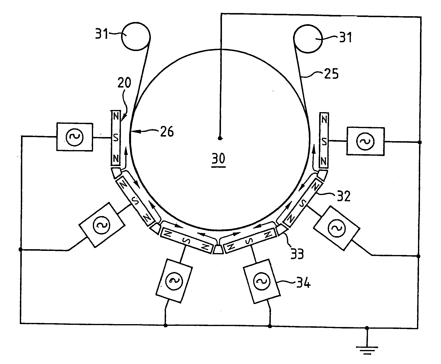
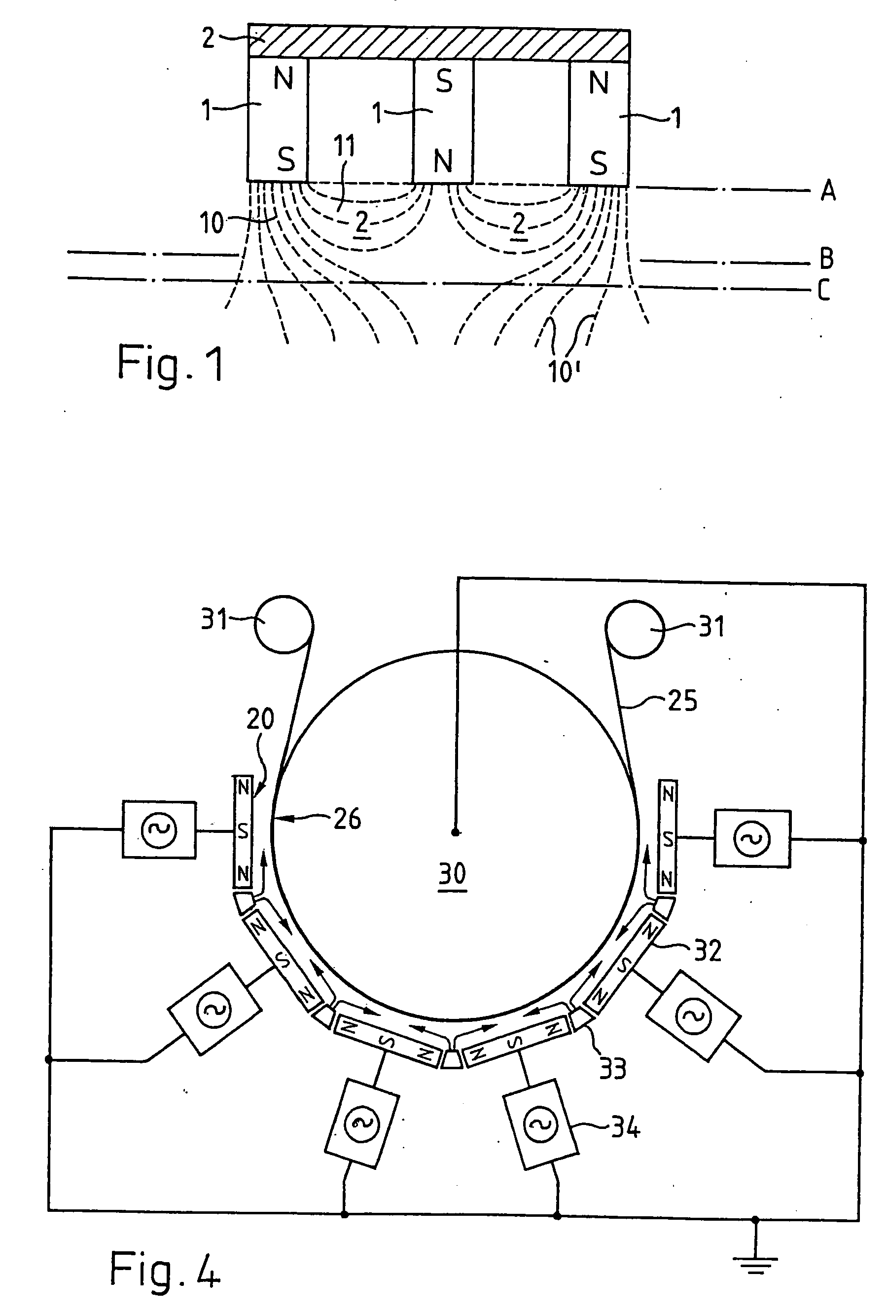
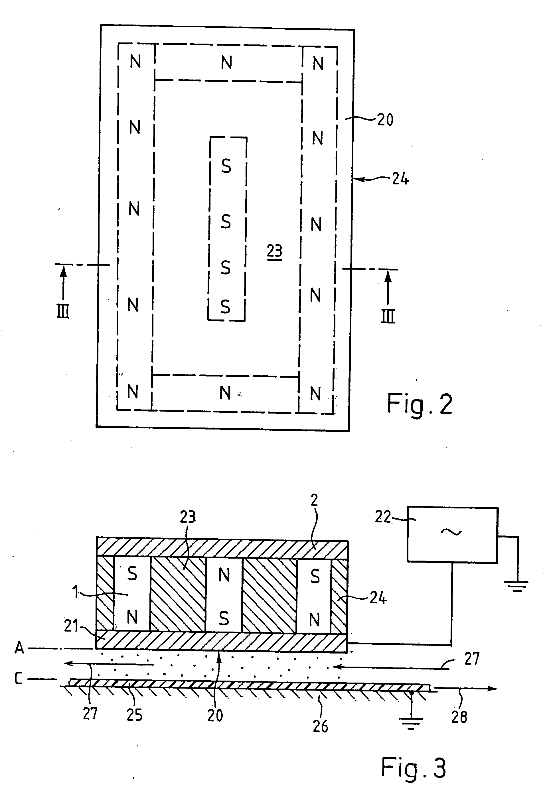
[0023] A device according to FIG. 4 with four magnetron electrodes according to FIGS. 2 and 3, each magnetron face being 600 mm long and 150 mm wide and each magnetron face comprising a central permanent magnet of a magnetic induction of ca. 100 Gauss (10−2 Tesla) and peripheral permanent magnets of ca. 200 Gauss being arranged around the central magnet with a distance between the poles of ca. 50 mm is used for coating a polymer film with silicon oxide using a plasma derived from a process gas mixture comprising an organosilicon compound and oxygen. The magnetron faces are positioned at a distance from the drum circumferential surface of ca. 60 mm (visibly such that there is a narrow bright band of plasma running beyond the tunnels along the substrate showing towards the substrate a regular intensity not being dependent on the tunnel positions). The magnetrons are powered with a total of 14 kW per m2 of magnetron face at a frequency of 40 kHz. The deposition rate such achieved is ca...


PUM

PropertyMeasurementUnit
Fractionaaaaaaaaaa
Fractionaaaaaaaaaa
Lengthaaaaaaaaaa

Abstract

A device for carrying out a plasma enhanced process includes, within a vacuum chamber, at least one magnetron electrode (32) constituting an unbalanced magnetron having a flat magnetron face (20) with peripheral and central magnetic poles of opposite polarities connected to a source (34) of alternating voltage. The device further includes a device for positioning a substrate (25), the substrate having a surface to be treated facing the magnetron face (20), and a gas supply device for supplying a process gas or process gas mixture to the space between the magnetron face (20) and the treated surface. The distance between the magnetron face (20) and the treated surface is adapted to the magnetic field created by the magnetron electrode (32) such that there is a visible plasma band running between darker tunnels formed by magnetic field lines extending between peripheral and central magnetic poles of the magnetron face (20) and the treated surface, the plasma band having a minimum width but having homogeneous brightness towards the treated surface.

Description

BACKGROUND OF THE INVENTION [0001] 1. Field of the Invention [0002] The invention relates to a device for carrying out a plasma enhanced process, in particular a plasma enhanced chemical vapour deposition. The device serves e.g. for coating one side of a web of film or sheet material, in particular for coating a web of polymer film with silicon oxide in order to improve its barrier properties. [0003] 2. Description of Related Art [0004] It is known e.g. from the publication EP-299754 (BOC) to deposit a thin film of silicon oxide on a substrate in a plasma enhanced chemical vapour deposition process. According to this publication a vacuum chamber is provided in which the electrically isolated substrate is positioned to face a magnetron being powered with an alternating voltage. A stream of a process gas mixture consisting of an organosilicon compound, oxygen and an inert gas (e.g. argon or helium) is flown into the space between the face of the magnetron and the substrate and the pla...

Claims


Application Information

Patent Timeline
IPC IPC(8): C23C16/00C23C16/509H01J37/32
CPCC23C16/509H01J37/3266H01J37/32009H01J37/32
Inventor FAYET, PIERREJACCOUD, BERTRAND
Owner TETRA LAVAL HLDG & FINANCE SA
Why Eureka
Eureka Blog
Learn More