
Method for control of yarn processing equipment

Inactive Publication Date: 2006-01-12
EI DU PONT DE NEMOURS & CO
View PDF40 Cites 6 Cited by
  • Summary
  • Abstract
  • Description
  • Claims
  • Application Information

AI Technical Summary

Benefits of technology

[0019] This invention comprises a computer-implemented method and program for starting each of at least three separately controllable roll-sets used for processing a yarn Y in a stretch-break process. Each roll-set comprises at least two rolls. Under the method of the present invention, for each roll-set, the speed of each roll is changed from an initial condition to a steady state condition in accordance with a predetermined sequence and in coordination with a change in speed of at least one of the other rolls, such that complete breakage of a yarn Y being processed in a stretch-break process is minimized.

Problems solved by technology

The production throughput of such a machine is relatively limited.
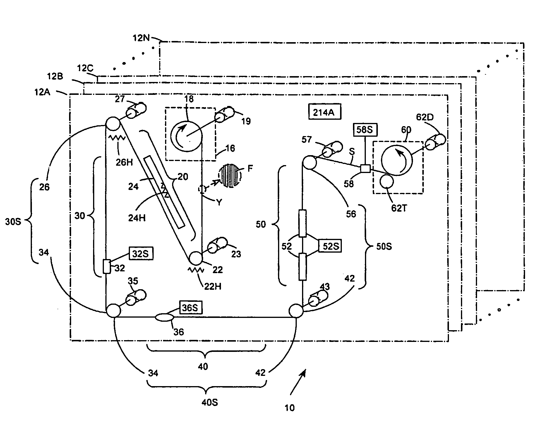
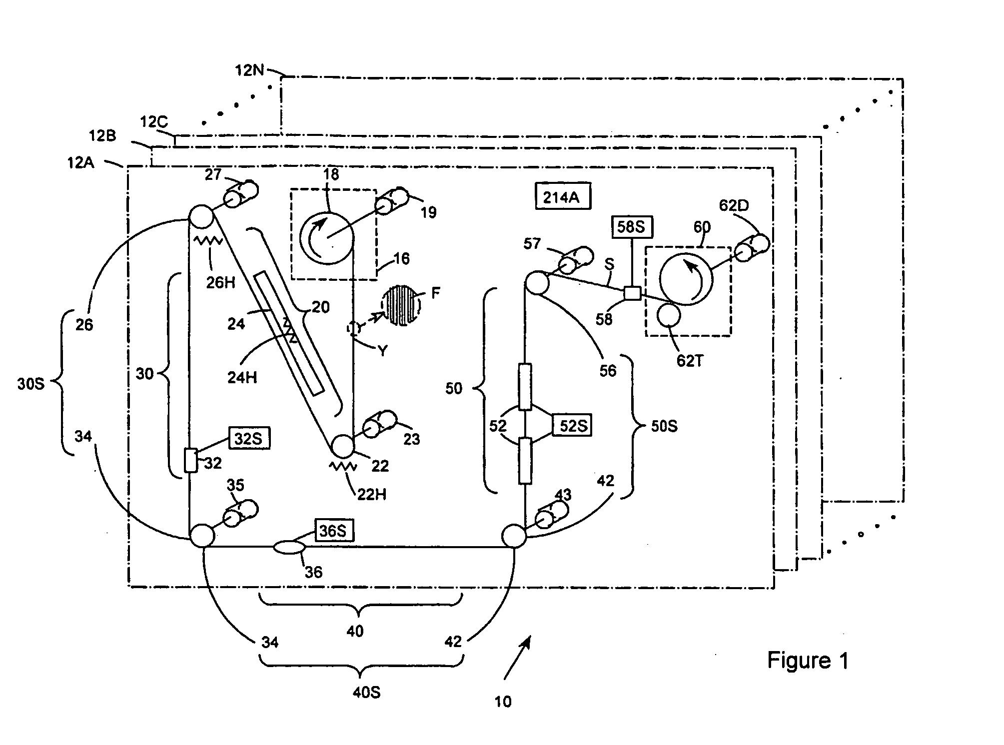
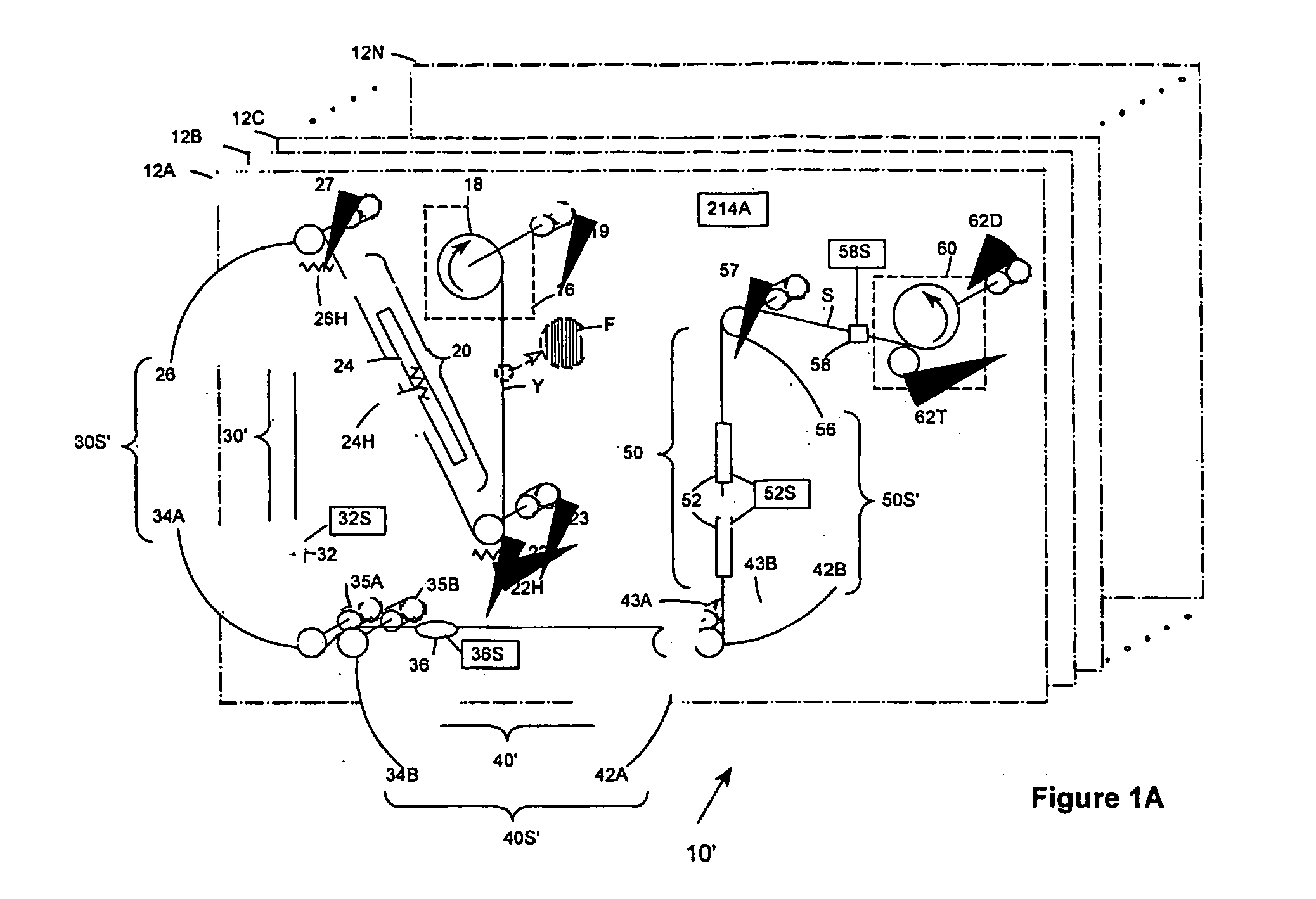
The stretch-break process as implemented in the apparatus 10 is particularly difficult to start, since the dynamic stretching and breaking properties of a yarn differ at various speeds and differ from its static properties.
Aggressive starting could result in simultaneous complete breakage of all filaments in either zone, resulting in loss of string-up of the yarn through the apparatus and generation of waste product.
Startup is particularly complicated by the interaction of process parameters.

Method used


Image

  • Method for control of yarn processing equipment
  • Method for control of yarn processing equipment
  • Method for control of yarn processing equipment

Examples


Embodiment Construction

[0030] Throughout the following detailed description similar reference characters refer to similar elements in all figures of the drawings.

[0031]FIG. 2 is a detailed block diagram of a control system 110 comprising a computer 112 and associated controller(s) 118 for executing a program in accordance with the method of the present invention to control each position 12A through 12N of the multi-position stretch-break apparatus 10 in accordance with a predetermined recipe. The control system 110 may be implemented using a standard desk-top personal computer 112 and one or more commercially available Programmable Logic Controllers (PLCs) 118.

[0032] The computer 112 comprises a central processing unit (CPU) 124, a memory 126, an operator display 128, a keyboard 142 and mouse 144 for operator input, an input-output interface 130 and an associated storage device 116 connected by a data and control bus 122. The memory 126 may be implemented as random access memory (RAM) or another suitabl...


PUM

PropertyMeasurementUnit
Fractionaaaaaaaaaa
Fractionaaaaaaaaaa
Fractionaaaaaaaaaa

Abstract

A method for starting or stopping each of at least two separately controllable roll-sets (22, 26, 34, 56) used for processing a yarn (Y) in a stretch-break process, each roll-set comrpising at least two rolls, the method is characterized by the step of each roll-set, changing the speed of each roll from an initial condition to a steady state condition in accordance with a predetermined sequence and in coordination with a change in speed of at least one of the other rolls, such that simultaneous complete breakage of a yarn (Y) being processed in a stretch-break process is minimized.

Description

FIELD OF THE INVENTION [0001] The present invention relates to control of yarn processing equipment in a stretch-break process and in particular to a method for starting the process in a coordinated manner. BACKGROUND [0002] The textile industry utilizes multi-positional commercial spinning machines capable of winding multiple spindles of identical product. One type of commercial yarn producing machine, known as a ring spinning machine, directly produces a staple yarn. The production throughput of such a machine is relatively limited. [0003] Another direct spinning apparatus, which for the purpose of this application is referred to as a “stretch-break” apparatus, improves throughput by producing staple yarn directly from a multi-filament yarn feed in a continuous operation. Shown within the dotted box in FIG. 1 is a schematic view of the functional and enabling elements of a single position 12A of a stretch-break apparatus generally represented by reference character 10. One or more...

Claims


Application Information

Patent Timeline
IPC IPC(8): G06F19/00D01G1/08
CPCD01G1/08G05B2219/49307G05B2219/45193G05B19/4163D01G1/10
Inventor SCOTT, GREGORY JAMESPERROTTO, JOSEPH ANTHONYSIMMONDS, GLEN EDWARDBRYSON, RICHARD DAVISCORCORAN, WILLIAM ROBERTWALKER, WILLIAM CHARLES
Owner EI DU PONT DE NEMOURS & CO
Learn More