Backup system and method for production of pressurized gas

a technology of pressurized gas and back-up system, which is applied in the direction of machines/engines, machine/engine discharging methods, lighting and heating apparatus, etc., can solve the problems of capital-intensive solutions, fast response time, and provide a very fast response tim

Inactive Publication Date: 2006-01-19
AIR LIQUIDE PROCESS & CONSTRUCTION INC
View PDF11 Cites 22 Cited by
  • Summary
  • Abstract
  • Description
  • Claims
  • Application Information

AI Technical Summary

Benefits of technology

[0015] In this way, a small portion of the produced liquid is diverted from the main flow through valve 18 and main heat exchanger 16 through valve 20. This small portion may typically be less than five percent of the produced liquid and may often be less than or much less than one percent. This extracted liquid which is already compressed at the appropriate pressure by pump 14 is transferred through bypass line 30 to the inlet of backup vaporizer 40 where it is permanently vaporized. The so vaporized gas passes through normally open valve 42 to the produced gas at outlet 50 of the plant and is thereby recombined with the gaseous product coming from main heat exchanger 16 through valve 22. Thus, the diverted liquid is not lost and is therefore efficiently utilized.
[0018] Except for bypass line 30, the path downstream of valve 20 is the regular transfer line to liquid storage tank 26 which may be used to store sufficient liquid in liquid storage tank 26 for the time the backup system is to be used. The constant and / or controlled flow through the path downstream of valve 20 and through bypass line 30 maintains the transfer line full of liquid, and maintains backup vaporizer 40 in cold stand-by, thereby allowing the backup system to react immediately to any flow to be vaporized.
[0020] It will be noted that for the case of liquid oxygen being vaporized to produce high-pressure gaseous oxygen and / or a cold box architecture sometimes called “side by side” type, the liquid inventory in main vaporizer 16 is not spoiled by the liquid falling from the low pressure distillation column in the case of trip. Thus, the liquid can be used as a clean source of liquid to be vaporized in backup vaporizer 40, again increasing the efficiency of the backup system.
[0027] Thus, a method is also provided for operating gas production system 10 which comprises a normally operating gas producing system and a backup gas production system. The method provides that changeover from a main or normally operating gas production system to a backup gas production system occurs in a way that minimizes pressure fluctuations and maintains efficient operation. In one embodiment, the method may comprise producing a liquefied gas stream in a normally operating air separation unit 11, pumping the liquefied gas stream with at least one normally operating pump 14 into at least one normally operating heat exchanger 16. Other steps may comprise vaporizing the liquefied gas stream in the normally operating heat exchanger 16 to produce an output product stream. In one embodiment, the method comprises diverting a small portion of the liquefied gas stream, e.g., less than five percent. The method may further comprise directing at least a portion of the diverted liquefied gas stream into backup heat exchanger 40 to maintain backup heat exchanger 40 in a cold standby mode. In a preferred embodiment, the output of backup heat exchanger 40 is combined with the output product stream. The method may further comprise providing that a pressure at an inlet of backup heat exchanger 40 is approximately equal to a pressure at an inlet of main heat exchanger 16 during normal operation to maintain backup heat exchanger and the liquid transfer lines thereto in a cold startup mode for immediate operation and so that gas vaporized in backup heat exchanger 40 is at the desired regulated pressure. The method may further comprise changing from normal operation to backup operation by shutting off flow of the liquefied gas stream to normally operating or main heat exchanger 16, and diverting all of the remaining liquefied gas stream to backup heat exchanger 40. Other steps may comprise at least temporarily continuing to pump all of the liquefied gas stream with at least one normally operating process pump 14. The method may further comprise subsequently turning on at least one backup pump 34. In one embodiment, the method may further comprise providing that normally operating pump 14 and backup pump 34 are temporarily simultaneously on during the changing from normal operation to the backup operation. In one presently preferred embodiment, the method may further comprise storing at least a portion of the diverted liquefied gas stream in liquid storage tank 26. The method may further comprise providing bypass line 30 around liquid storage tank 26 to connect with backup heat exchanger 40.

Problems solved by technology

This method provides a very fast response time, but is a capital-intensive solution.
This solution provides a relatively fast response time, but is also capital intensive and is limited in the range of operating pressure permitted by this solution.
This method has a very fast response time, but it is liquid and energy consuming.

Method used


Image

  • Backup system and method for production of pressurized gas
  • Backup system and method for production of pressurized gas
  • Backup system and method for production of pressurized gas

Examples


Embodiment Construction

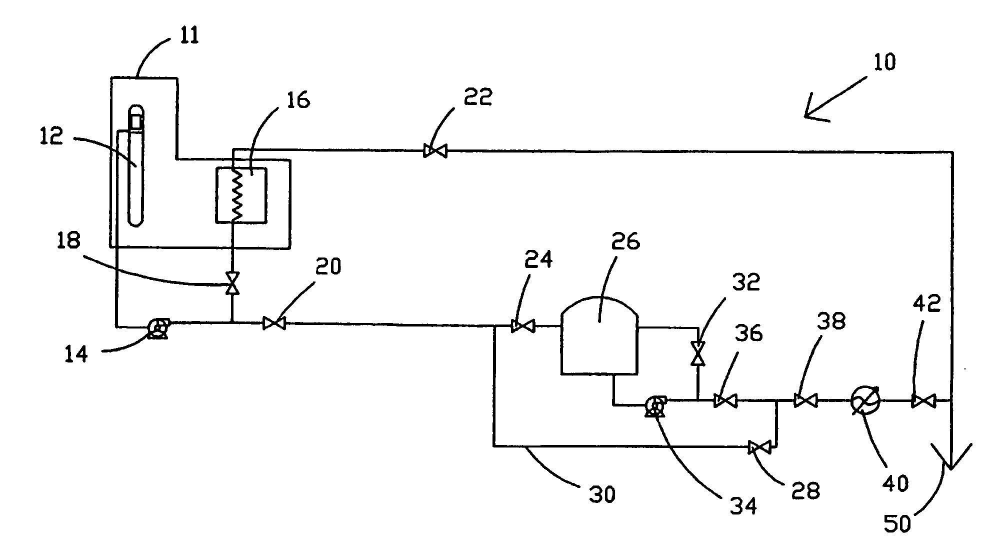
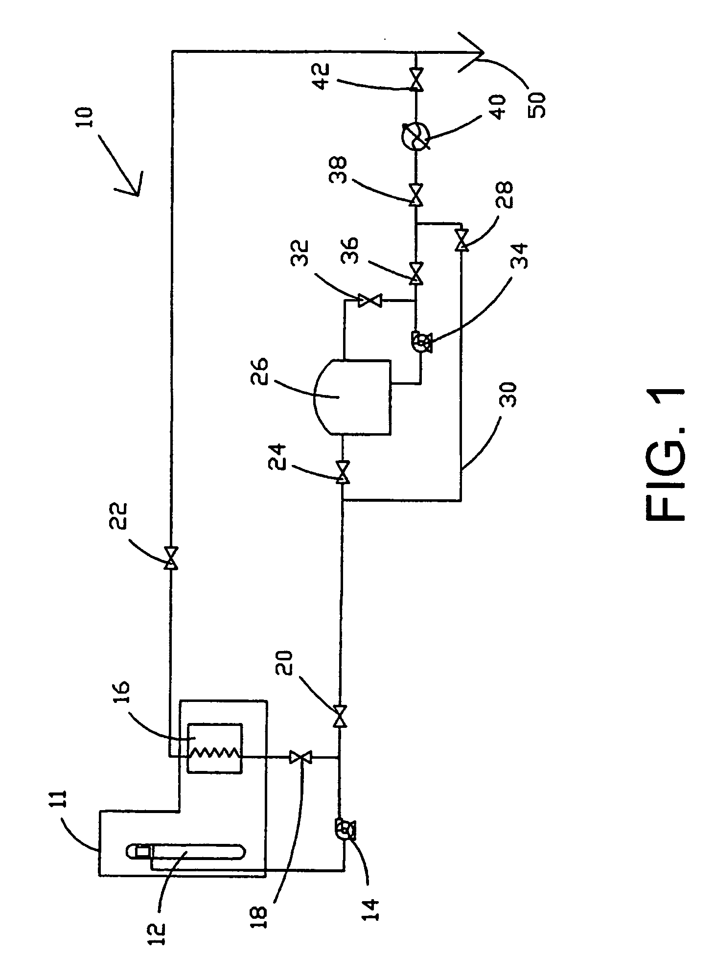
[0012] Referring now to FIG. 1, there is shown gas production system 10 which comprises a main and backup gas production system in accord with the present invention.

[0013] During normal operation of gas production system 10, liquid such as liquid oxygen and / or other product(s) is separated and extracted in air separation unit 11. Air separation unit 11 may comprise one or more distillation columns 12, heat exchangers, vaporizers, pumps, valves, or other separators, vessels, or components that may normally be utilized for this purpose by one of ordinary skill in the art. The liquid so extracted is then normally compressed by pump 14 and subsequently vaporized under high pressure in main heat exchanger 16.

[0014] A backup system for gas production in system 10 is provided downstream of valve 20. Valve 20 controls liquid flow to the backup or transfer flow line. In accord with one embodiment of the present invention, system 10 does not rely for backup only on having backup pump(s) 34 ...


PUM


Abstract

Systems and methods are disclosed for a gas production system to efficiently maintain a pressure of a gaseous output stream within a tight pressure range when the system changes normal operation to backup operation. In one preferred embodiment, during normal operation a backup vaporizer is kept in cold standby by directing a small portion of a liquefied gas stream away from the main heat exchanger to the backup vaporizer. In this way, the backup vaporizer is able to respond immediately to a shutdown of the main gas production system. During normal operation, the output of the backup vaporizer is recombined with the gaseous output stream to any avoid loss of product thereby increasing efficiency.

Description

FIELD OF INVENTION [0001] The present invention provides a process for production of pressurized gas and, more specifically, provides a fast response, cost-efficient backup system for producing pressurized gas. BACKGROUND OF THE INVENTION [0002] Industrial gas consumers frequently request a relatively tight control in pressure variations of pressurized gas produced from a gas production facility. It is desirable that pressure variations remain within these relatively tight limits regardless of disruptive events that inevitably occur at the industrial facility, at least upon occasion. For example, such events may include stopping operation of the air separation unit for scheduled as well as non-scheduled plant shutdowns. [0003] Similarly, it is also optimal to other users of pressurized gas to minimize pressure variations and to maintain the pressures in a desired range. [0004] In modern air separation units, internal compression processes may be utilized to directly obtain gases und...

Claims


Application Information

Patent Timeline
Patent Type & Authority Applications(United States)
IPC IPC(8): F17C9/02F02B43/00F25J1/00
CPCF25J3/04084F25J3/0409F25J3/04412F25J3/04769F25J3/04824F25J2290/62F25J2235/42F25J2235/50F25J2245/42F25J2245/50F25J2250/50F25J3/04878
Inventor BRIGLIA, ALAINMINISCLOUX, DIDIER
Owner AIR LIQUIDE PROCESS & CONSTRUCTION INC
Why Eureka
Try Eureka