Refractive index determination by micro interferometric reflection detection

Inactive Publication Date: 2006-01-19
DANMARKS TEKNISKE UNIV +1
View PDF10 Cites 33 Cited by
  • Summary
  • Abstract
  • Description
  • Claims
  • Application Information

AI Technical Summary

Problems solved by technology

Not all are equally fast since sample preparation often is extensive and requires time-consuming steps such as chemical tagging of molecules16.

Method used


Image

  • Refractive index determination by micro interferometric reflection detection
  • Refractive index determination by micro interferometric reflection detection
  • Refractive index determination by micro interferometric reflection detection

Examples


Embodiment Construction

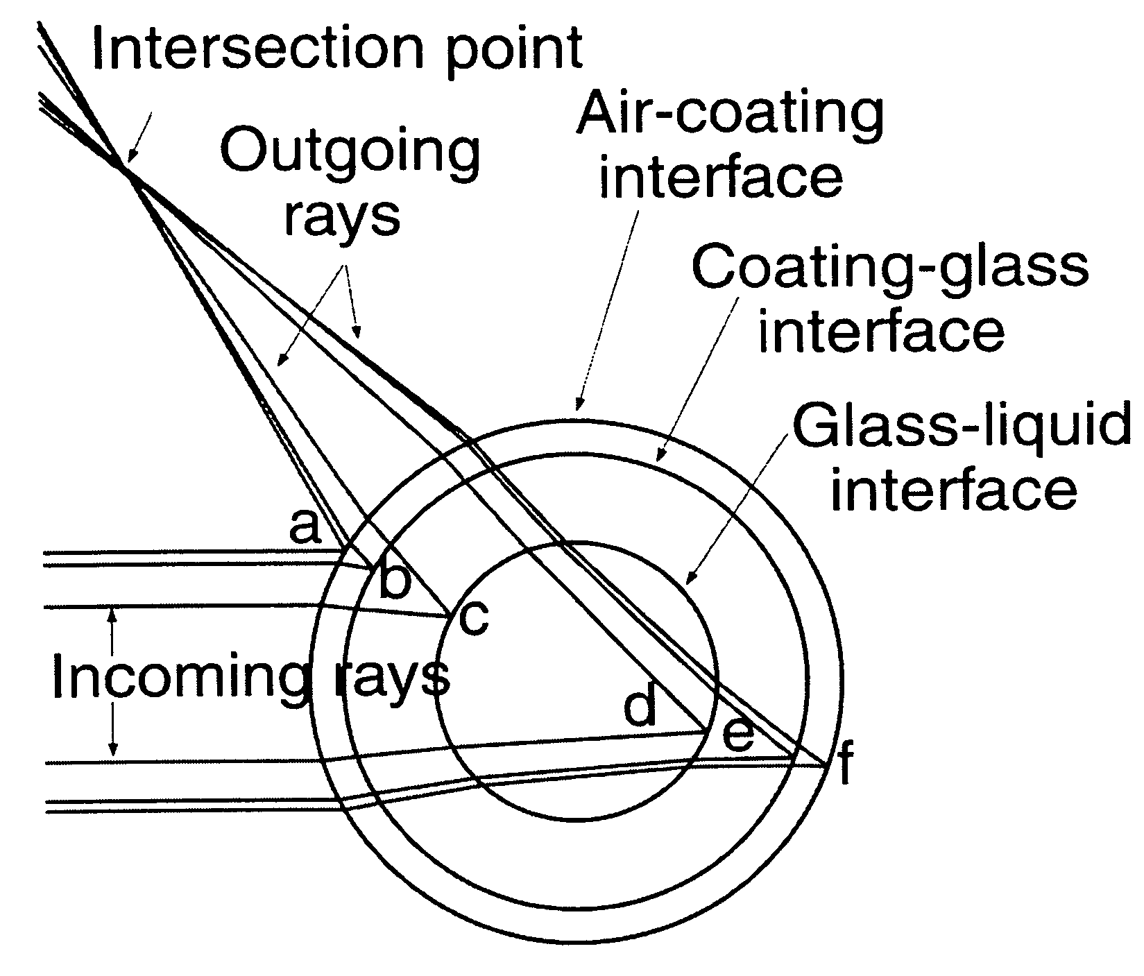
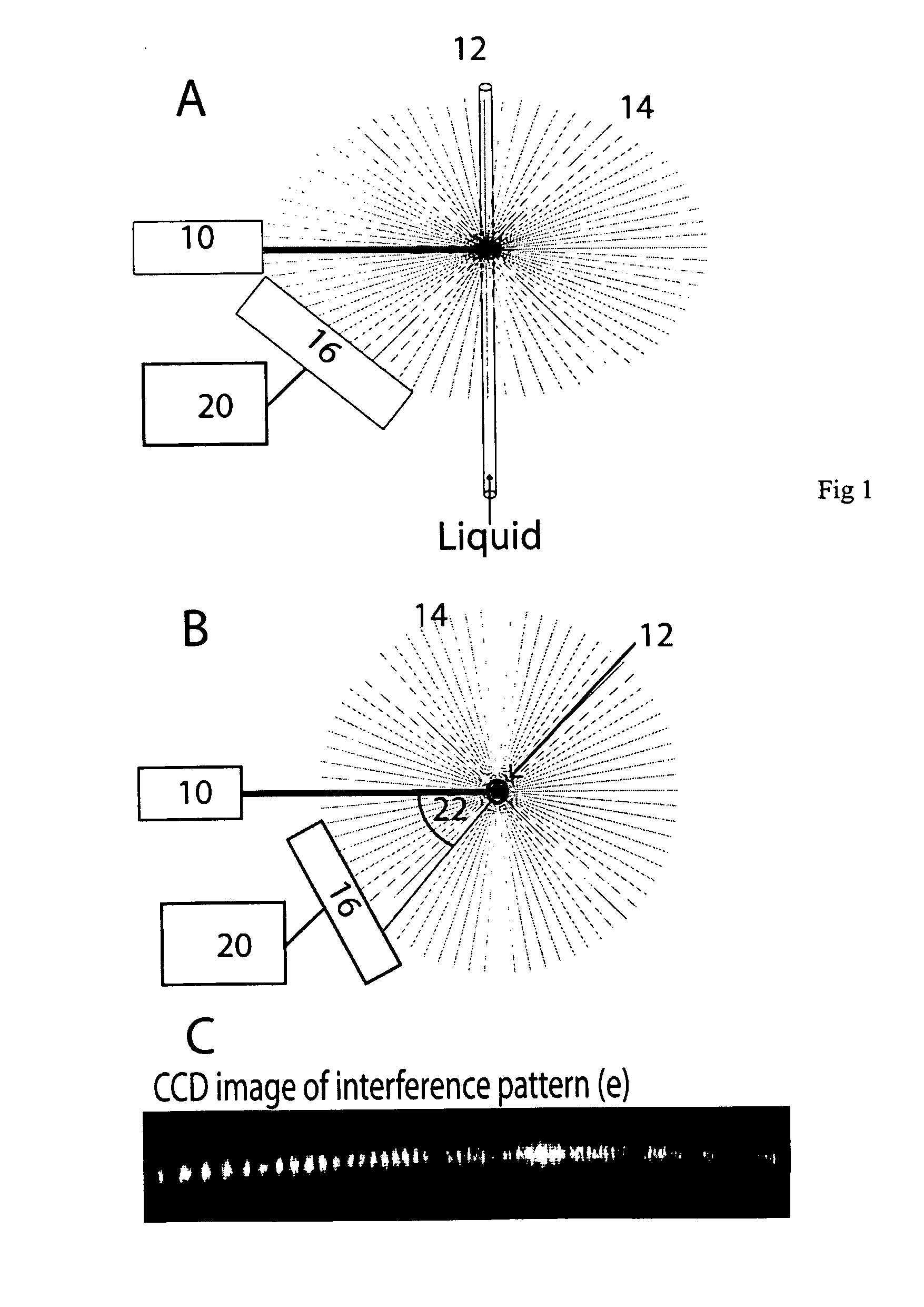
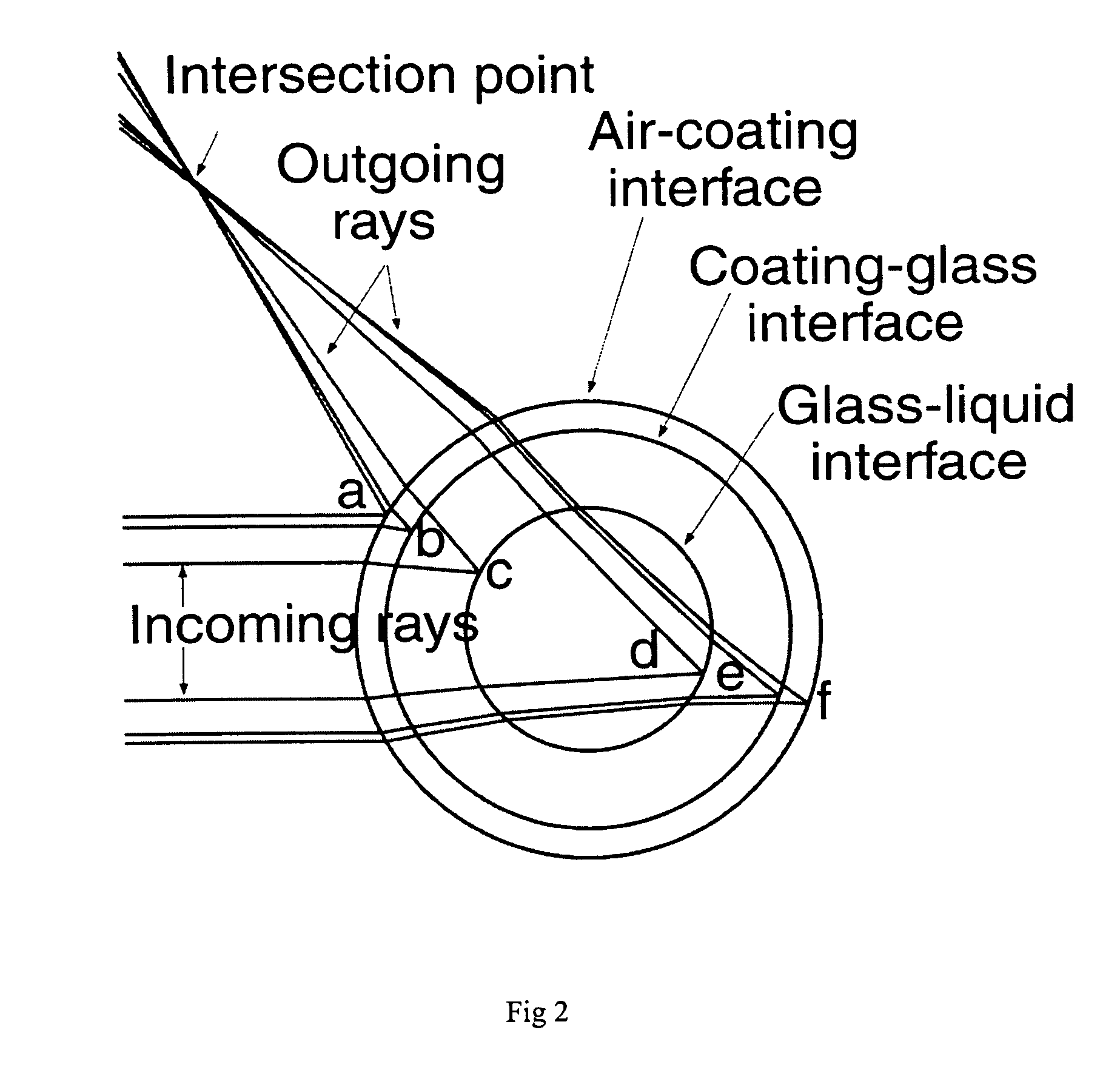
[0044] A typical MIBD scheme as previously known is shown in FIG. 1. The system consists of a laser 10 that impinges its beam on a capillary tube 12 filled with a liquid of which one wants to measure refractive index, thereby creating an interference pattern 14. This interference pattern, which changes with changes in the liquid's refractive index, is then measured using a CCD detector 16. A typically observed interference pattern in the reflection direction is seen in C. This is analyzed by data processing means 20.

[0045] The demonstrated sensitivity of 10−7 is reached by following the displacement of the individual light fringes of the interference pattern within 0-3 angular degrees24 from the directly back reflected direction, as one changes the refractive index of the liquid. The fringe pattern is periodic in refractive index space with a period of the order of 10−3. This limits the dynamic measurement range to the order of 10−3, which for many purposes requires additional know...


PUM


Abstract

A method and an apparatus for absolute refractive index measurements are disclosed, wherein a beam of spatially coherent laser light is directed perpendicularly on to a side of a capillary tube (12) and back reflected light is detected (16) over a range of angles (22) with respect to the incident light beam. The refractive index of a liquid contained in the capillary is determined from the angle at which a marked change in the intensity of the interference fringes of the interference pattern formed by said back reflected light is observed or from the amplitude of a low frequency component of the angular variation of the intensity of interference fringes.

Description

CROSS REFERENCE TO RELATED APPLICATIONS [0001] This application is a Continuation, under 35 U.S.C. 120 and 365(c), of copending International Application No. PCT / US2003 / 025849, which was filed on Sep. 4, 2003 and designates the United States.BACKGROUND OF THE INVENTION [0002] 1. Field of the Invention [0003] The present invention relates to methods and apparatus for the determination of refractive index, including the determination of the absolute value of the refractive index of a sample. [0004] 2. Description of the Background Art [0005] Rapid monitoring and detection of ultra small volume samples is in great demand1. Two major areas are environmental monitoring2 and point of care detection3,4. This covers a huge range from drinking water quality5 and food quality6 to determination of glucose7 and urea8. Several detection techniques have the capability to perform fast measurements on small amounts of analyte. Well-established techniques include electrochemistry9,10 mass spectromet...

Claims


Application Information

Patent Timeline
Patent Type & Authority Applications(United States)
IPC IPC(8): G01B9/02
CPCG01N21/45
Inventor BORNHOP, DARRYL J.ANDERSEN, PETER ESKILSORENSEN, HENRIK SCHIOTTPRANOV, HENRIK
Owner DANMARKS TEKNISKE UNIV
Why Eureka
Try Eureka