
Confocal microscope, fluorescence measuring method and polarized light measuring method using cofocal microscope

Inactive Publication Date: 2006-01-19
JAPAN SCI & TECH CORP
View PDF2 Cites 55 Cited by
  • Summary
  • Abstract
  • Description
  • Claims
  • Application Information

AI Technical Summary

Benefits of technology

[0015] The object of the present invention is, referring to the above-mentioned problems, to offer a confocal microscope using liquid crystal device, the method of fluorescent measurement of microarray substrates by the confocal microscopy using liquid crystal device, and to a method of polarized light measurement by the confocal microscopy using liquid crystal device, which are of high sensitivity, excel in resolution in the horizontal and the depth directions, and are capable of dynamic observation in a wide range.

Problems solved by technology

Incidentally, the confocal microscope of a sample scanning type of a conventional example 1 conducts monofocal detection, and therefore scanning is required for wide range observation, thereby real time observation of fluorescence and others is difficult.
Because of this, the illuminated light intensity distribution becomes non-uniform, which causes a problem that the horizontal resolution of the observed image is lowered.
Further, as an application of the confocal microscope, the largely dispersed fluoroescent signals from DNA chips cannot be observed on a detector at one time.
However, since X-Y scanning for the number of pixels is required for turning on and off each pixel of a liquid crystal, scanning over one image takes time, and it is difficult to detect fluorescence and the like of whole of the sample in real time.
Although the time for scanning is made shorter than the case of monofocus of the multi-confocal microscope of a conventional example 1, the scanning is necessary to observe wide range, thereby a real time observation of fluorescence or the like is difficult.

Method used


Image

  • Confocal microscope, fluorescence measuring method and polarized light measuring method using cofocal microscope
  • Confocal microscope, fluorescence measuring method and polarized light measuring method using cofocal microscope
  • Confocal microscope, fluorescence measuring method and polarized light measuring method using cofocal microscope

Examples


first embodiment

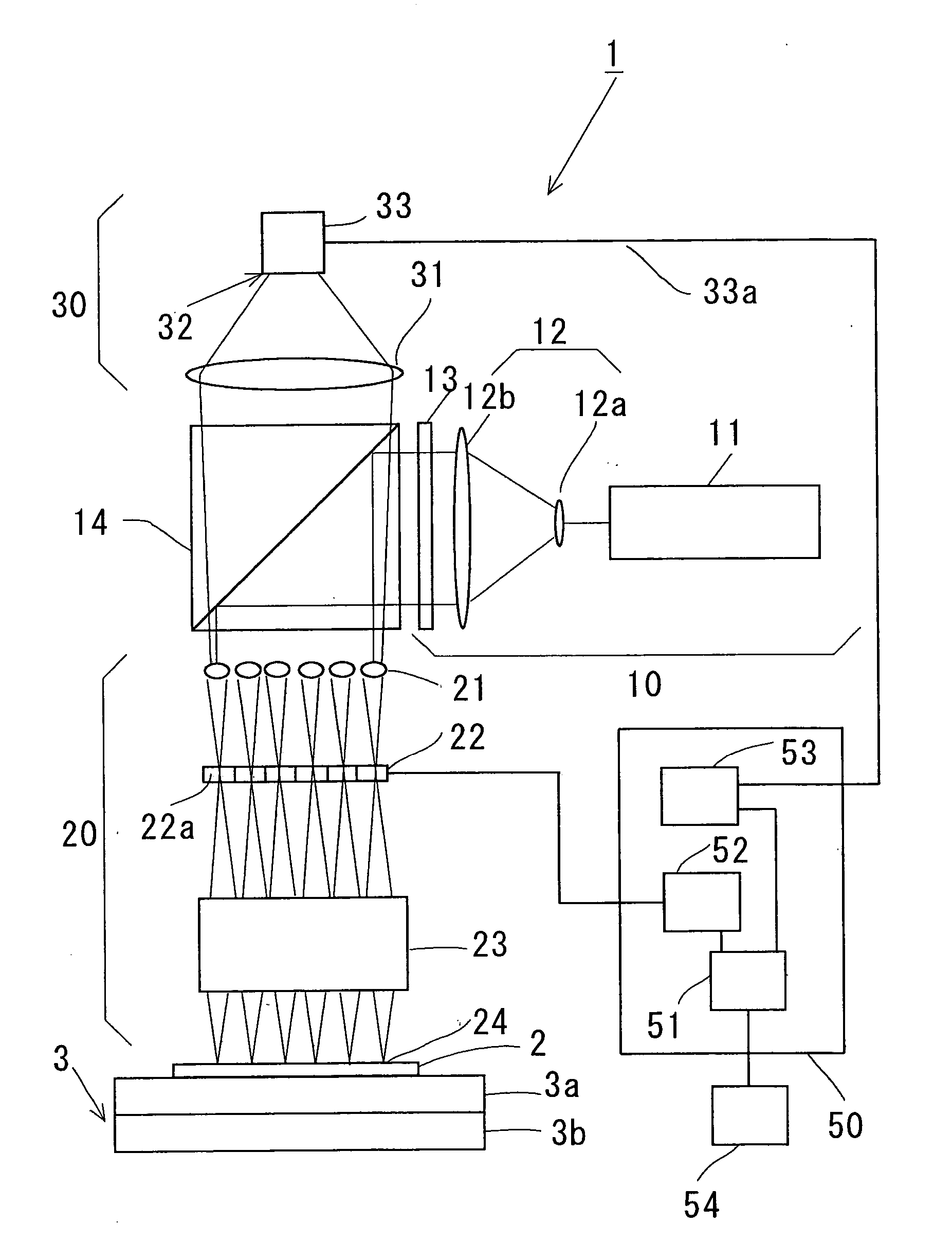
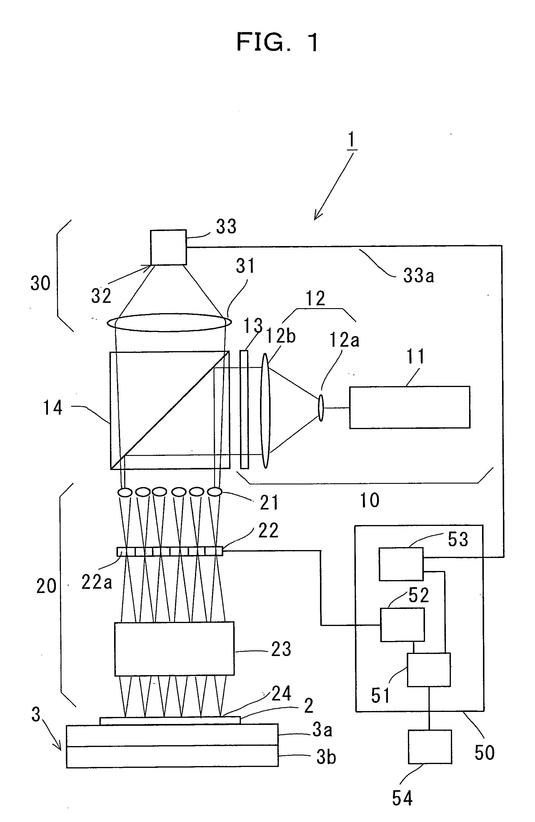
[0069] Next, a modified example of the confocal microscope using liquid crystal of the present invention is shown. FIG. 4 is a view illustrating another makeup of a confocal microscope using liquid crystal in accordance with the present invention. The difference of a confocal microscope 1′ shown in FIG. 4 from a confocal microscope 1 using liquid crystal shown in FIG. 1 is an inlet optical part 20. Other illuminating optical part 10, the light detecting part 30, the control part 50, and the stage 3 are all same as in FIG. 1, so that explanation is skipped. The inlet optical part 20 differs from that in FIG. 1 in that a second polarizer 25 is set in the lower part of the matrix type liquid crystal device 22.

[0070]FIG. 5 is a view briefly illustrating the functional effect of a polarizer 25 provided to the inlet optical part. As shown in FIG. 5, the parallel light 15 from the collimater 12 is illuminated after passing through the first polarizer 13, the microlens array 21, and the mat...

second embodiment

[0084] A modified example of the confocal microscope using liquid crystal of the present invention is shown next. FIG. 7 is a view illustrating another makeup of a confocal microscope using liquid crystal in accordance with the present invention. The difference of the illustrated confocal microscope using liquid crystal device 5′ from that of 5 as shown in FIG. 6 is an inlet optical part 20′. Since other illuminating optical part 10, the light detecting part 30′, the control part 50′, and the stage 3 are same makeup as in FIG. 6, the explanation is omitted. In this example, the inlet optical part 20′ differs from that of FIG. 6 in that the second polarizer 25 is located in the lower part of the matrix type liquid crystal device 22.

[0085] The function of said second polarizer 25 is, as explained in FIGS. 4 and 5, to change the illuminating light intensity by drive voltage of pixels 22a of the first matrix type liquid crystal device. Each pixel of the first matrix type liquid crystal ...

third embodiment

[0090]FIG. 9 is a diagrammatic view illustrating another example of the makeup of an illuminating optical part of a confocal microscope in accordance with the present invention. A illuminating optical part 60′ differs from the illuminating optical part 60 of FIG. 8 in that an acoustooptic modulator 68 is further provided between the illuminating light source 11 and the collimater 12. After the illuminating light source 11 is amplitude modulated (modulation frequency fAO) by the acoustooptic modulator 68, and is expanded to parallel light of the desired beam diameter by the collimater 12, the light amplitude is modulated (modulation frequency f2), so-called double amplitude modulated, by the matrix type liquid crystal device 64 for amplitude modulation. The acoustooptic modulator 68 can be modulated with much higher frequency than that of using the matrix type liquid crystal device for amplitude modulation (fAO>f1, f2).

[0091] The control part 70 differs from that of 50 in the confoca...


PUM


Abstract

The present invention relates to a confocal microscope and the measuring methods of fluorescence and the polarized light using the same, and said confocal microscope is provided with the inlet optical part (10, 10′) to let the polarized light from an illuminating light source (11) onto an object to be observed (2) via a matrix type liquid crystal device (22) provided with a microlens array (21) on its top part, and an objective lens (23), the light detecting part (30, 30′) to detect the reflected or the fluorescent light from the object to be observed, and the liquid crystal control subpart (52) to control a liquid crystal device (22), and it transmits the light passing through said microlens array (21) from each microlens to each pixel (22a) of the liquid crystal device (22), and makes a plurality of foci (24) on the object to be observed (2) by the objective lens (23), as well as controls polarization directions of the lights transmitted through each pixel of the liquid crystal device (22) using the liquid crystal control subpart (52) so that they are made mutually orthogonal.

Description

TECHNICAL FIELD [0001] The present invention relates to a confocal microscope used for fluorescent observation or the like of biological tissues and organisms, a confocal microscope using liquid crystal device, the method of fluorescent measurement of microarray substrates by the confocal microscope using liquid crystal device, and to the method of polarized light measurement by the confocal microscope using liquid crystal device, which are of high sensitivity, excel in resolution in the horizontal and the depth directions, and are capable of dynamic observation in a wide range. BACKGROUND ART [0002] Heretofore, confocal microscopes have been used for the observation of fluorescent luminescence from the biological tissue samples in which biological tissues and fluorescent reagents are added in the fields of study of biological science. Since confocal microscopes have high resolution in the depth direction, they are mainly used for three dimensional observation of biological samples....

Claims


Application Information

Patent Timeline
IPC IPC(8): G02B21/06G01N21/21G01N21/64G02B21/00
CPCG01N21/21G01N21/6445G01N21/6452G01N21/6458G02B21/0076G01N2021/6478G01N2201/0675G02B21/0024G02B21/0068G01N2021/6471G02B5/3016
Inventor HAYASHI, TERUTAKEMAEKAWA, KATSUHIROSHIBATA, TAKAYUKI
Owner JAPAN SCI & TECH CORP
Features
  • Generate Ideas
  • Intellectual Property
  • Life Sciences
  • Materials
  • Tech Scout
  • Unparalleled Data Quality
  • Higher Quality Content
  • 60% Fewer Hallucinations
Learn More