Overcurrent protection circuit

a protection circuit and overcurrent technology, applied in the direction of electric variable regulation, process and machine control, instruments, etc., can solve the problems of easy oscillation of circuits, adverse effects on circuit stability, affecting reliability, etc., and achieve the effect of quick sensing an overcurrent and without loss of circuit stability

Inactive Publication Date: 2006-01-19
ROHM CO LTD
View PDF7 Cites 35 Cited by
  • Summary
  • Abstract
  • Description
  • Claims
  • Application Information

AI Technical Summary

Benefits of technology

[0008] The present invention was developed in view of the aforementioned problems. It is therefore an object of the present invention to provide an overcurrent protection circuit which is capable of quickly...

Problems solved by technology

However, even with the transistor designed to have such a sufficient design margin, a short circuit may be developed in the output load circuit.
In this case, there was a problem that a large overcurrent exceeding the maximum allowable current would flow through the transistor, thereby affecting the reliability thereof.
However, as pointed out in the aforementioned document, the protection circuit having the current limiting function for sensing the current flowing through the transistor for feedba...

Method used


Image

  • Overcurrent protection circuit
  • Overcurrent protection circuit
  • Overcurrent protection circuit

Examples


Embodiment Construction

[0026] The invention will now be described based on preferred embodiments which do not intend to limit the scope of the present invention but exemplify the invention. All of the features and the combinations thereof described in the embodiment are not necessarily essential to the invention.

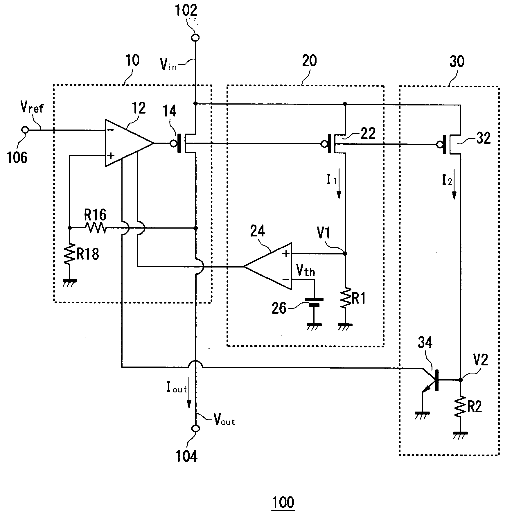
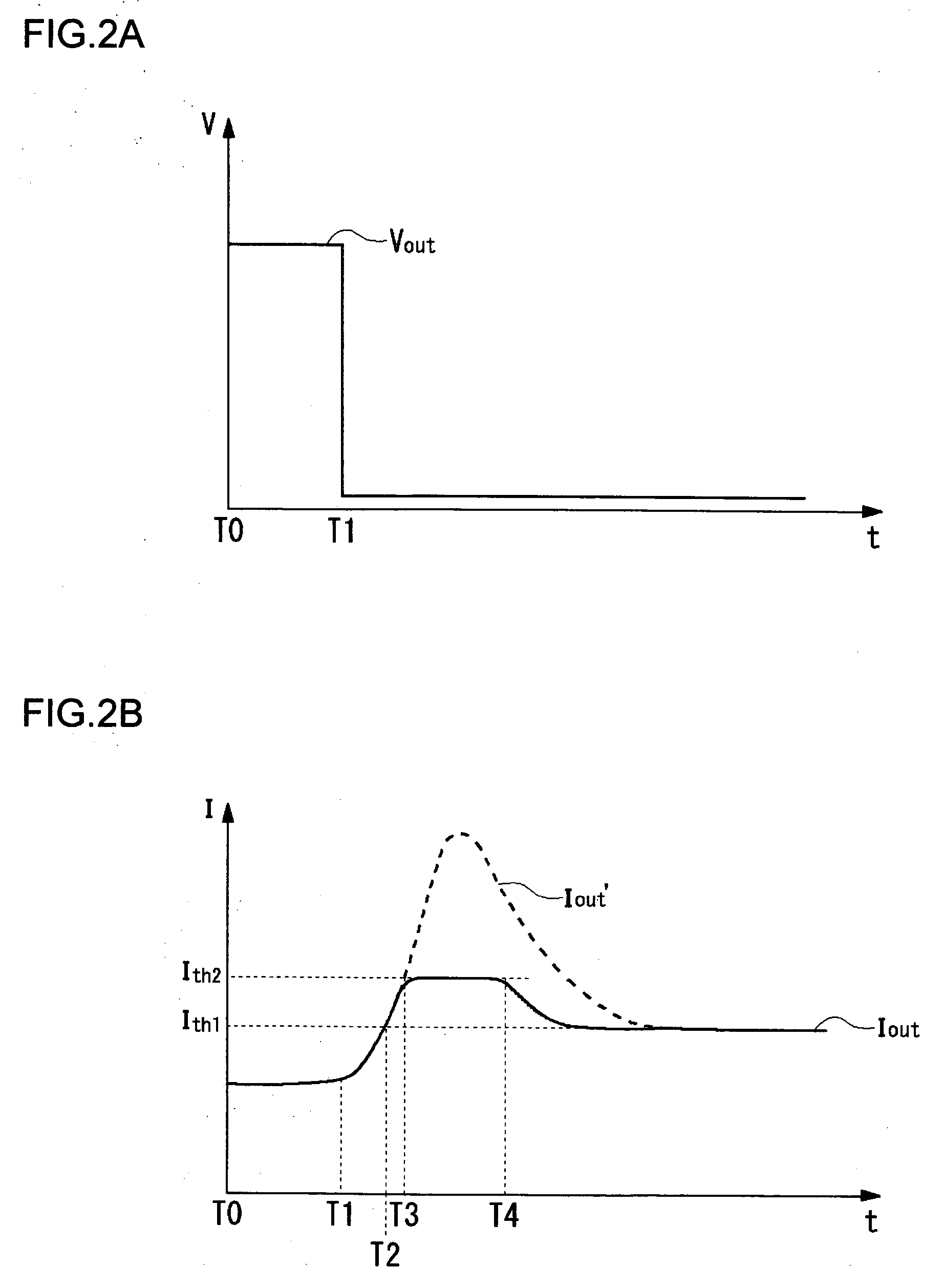
[0027]FIG. 1 is a circuit diagram showing a voltage generator circuit 100 according to an embodiment of the present invention. The voltage generator circuit 100 is a three-terminal voltage regulator for adjusting an output voltage to a constant value based on a reference voltage and includes an overcurrent protection circuit.

[0028]FIG. 4 is a block diagram showing the arrangement of an electronic apparatus 300 which incorporates the voltage generator circuit 100 of FIG. 1. For example, the electronic apparatus 300 may be a cellular phone, a PDA (Personal Digital Assistance), a digital still camera, or a CD player. The electronic apparatus 300 includes a battery 310, the voltage generator circuit...


PUM


Abstract

The voltage generator circuit includes a regulator, a first sensor circuit, and a second sensor circuit. The first sensor circuit includes a first transistor, a first resistor, and an error amplifier. When V1>Vth, the error amplifier senses an overcurrent condition to provide feedback to the operational amplifier to limit an output current. The second sensor circuit includes a second transistor, a second resistor, and a sensing transistor. When the output current exceeds a sense threshold current, the sensing transistor is turned ON to provide feedback to the operational amplifier 12 to limit the output current. The second sensor circuit has a higher setting of sense threshold current than does the first sensor circuit, while having a higher setting of sensing speed than does the first sensor circuit.

Description

BACKGROUND OF THE INVENTION [0001] 1. Field of the Invention [0002] The present invention relates to an overcurrent protection circuit, and more particularly to a circuit protection technique for protecting a voltage generator circuit used as a power supply circuit from overcurrents. [0003] 2. Description of the Related Art [0004] In regulators for stabilizing voltages or the like, used as an output transistor is the power MOSFET (Metal Oxide Semiconductor Field Effect Transistor), the IGBT (Insulated Gate Bipolar Transistor), the bipolar power transistor or the like. These transistors are designed to have a sufficient margin between the maximum allowable current and a current flowing during normal operation. [0005] However, even with the transistor designed to have such a sufficient design margin, a short circuit may be developed in the output load circuit. In this case, there was a problem that a large overcurrent exceeding the maximum allowable current would flow through the tran...

Claims


Application Information

Patent Timeline
IPC IPC(8): H02H3/08
CPCH03K17/0822H02H3/087H02H9/02H02M3/155G05F1/56H03F1/52
Inventor KITAGAWA, ATSUSHI
Owner ROHM CO LTD
Why Eureka
Try Eureka