High efficiency flyback converter

a high-efficiency, converter technology, applied in the direction of ac-dc conversion, efficient power electronics conversion, electric variable regulation, etc., can solve the problems of reducing the overall affecting the general power balance or total power use of the circuit, and the diode rectifier's forward voltage drop becoming the dominant power loss, etc., to achieve the effect of reducing the power loss

Active Publication Date: 2006-01-19
DET INT HLDG LTD
View PDF15 Cites 38 Cited by
  • Summary
  • Abstract
  • Description
  • Claims
  • Application Information

AI Technical Summary

Benefits of technology

[0009] In order to address the drawbacks of the prior art, the present invention provid

Problems solved by technology

In low-output-voltage converters, the conduction loss of the diode rectifier due to its forward voltage drop becomes the dominant power loss.
In certain conditions this loss can reach 50% of the total power loss.
The main drawback of the above presented approach is the cross-conduction (concurrent conduction) of the primary switch S1 and secondary synchronous rectifier S2 for the time intervals t0-t1, t2-t3 (see FIG. 1A), for CCM operation.
Another drawback

Method used


Image

  • High efficiency flyback converter
  • High efficiency flyback converter
  • High efficiency flyback converter

Examples


Embodiment Construction

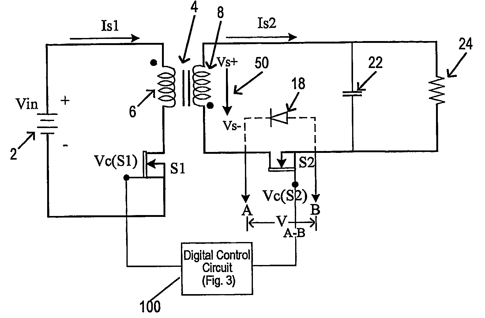
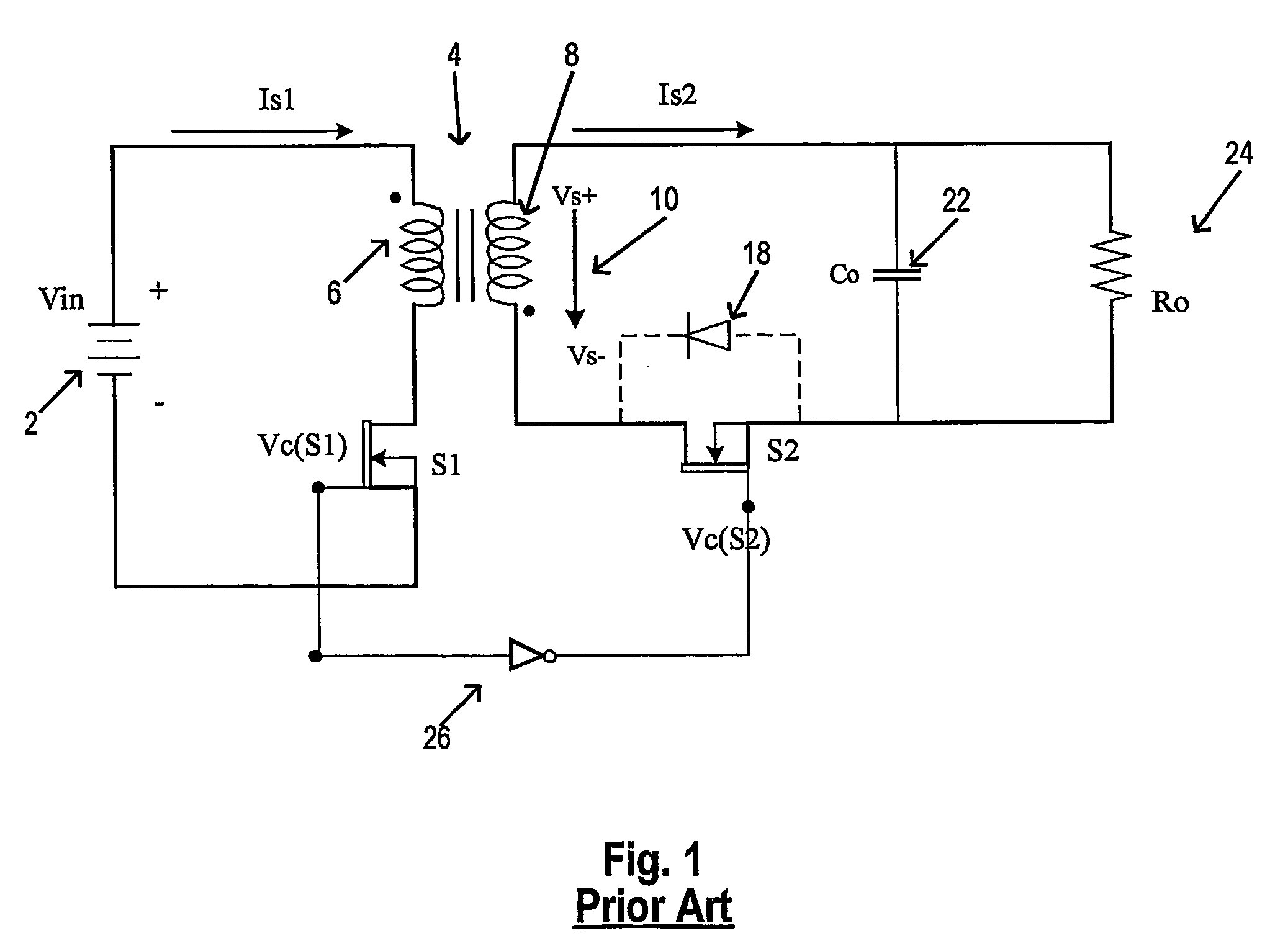
[0030] The approach used to control the synchronous rectifier of a DC-DC flyback converter according to this invention is first described in relation to the improved basic schematic of the flyback converter shown in FIG. 2. In the flyback converters of FIGS. 1 and 2, like elements bear like reference numerals. The voltage source 2 supplies the input circuit formed by the primary winding 6 of the power transformer 4 connected in series with the switching MOSFET S1. The switching transistor S1 is controlled by a signal Vc(S1). The output circuit of the flyback converter contains the secondary winding 8 of the power transformer 4 connected in series with the synchronous rectifier S2 and the output load 24. The output voltage obtained on the load is filtered by the capacitor 22. The body diode 18 of the synchronous rectifier is also represented as it plays a role in the operation of the circuit. According to one preferred embodiment of this invention, besides the main switch control sig...


PUM


Abstract

A DC-DC flyback converter that has a controlled synchronous rectifier in its secondary circuit, which is connected to the secondary winding of a main transformer. A main switch (typically a MOSFET) in the primary circuit of the converter is controlled by a first control signal that switches ON and OFF current to the primary winding of the main transformer. To prevent cross-conduction of the main switch and the synchronous rectifier, the synchronous rectifier is turned ON in dependence upon a signal derived from a secondary winding of the main transformer and is turned OFF in dependence up a signal derived from the first control signal. In one embodiment the first control signal is inverted and delivered to a logic circuit along with the voltage across the main transformer secondary winding and the voltage across the synchronous rectifier. In a further embodiment the first control signal is differentiated and supplied to a control primary winding wound on the outer flux paths of a main transformer core that has a center flux path on which is wound the main transformer primary and secondary windings. A control secondary winding is wound on the outer flux paths in current canceling relation as to flux conducted from the center flux path into the outer flux paths. The control signal for the synchronous rectifier is taken from the output of the control secondary winding in this latter embodiment.

Description

CROSS REFERENCE TO RELATED APPLICATIONS [0001] Priority is claimed from U.S. provisional patent application Ser. No. 60 / 372,280 entitled “High Efficiency Flyback Converter” filed Apr. 12, 2002 in the name Ionel D. Jitaru. That application is incorporated herein by reference.FIELD OF THE INVENTION [0002] This invention relates to DC-DC flyback converters and more particularly to a DC-DC flyback converter having a controlled synchronous rectifier in a secondary circuit and the means of controlling the synchronous rectifier. BACKGROUND OF THE INVENTION [0003] Of available DC-DC converters used for power conversion purposes, the flyback converter is the most simple. Its minimum configuration consists of only a switch, a transformer, a diode and two capacitors (one at the input port and the second one at the output port). In low-output-voltage converters, the conduction loss of the diode rectifier due to its forward voltage drop becomes the dominant power loss. In certain conditions this...

Claims


Application Information

Patent Timeline
IPC IPC(8): H02M3/335
CPCH02M1/32H02M1/38H02M3/33592Y02B70/1491H02M2001/0048Y02B70/1475H02M2001/0012H02M1/0012H02M1/0048Y02B70/10
Inventor JITARU, IONEL D.
Owner DET INT HLDG LTD
Why Eureka
Try Eureka