Method and architecture for compressing image data acquired from a bayer color filter array

Inactive Publication Date: 2006-01-19
STMICROELECTRONICS SRL
View PDF8 Cites 12 Cited by
  • Summary
  • Abstract
  • Description
  • Claims
  • Application Information

AI Technical Summary

Benefits of technology

[0024] This, coupled to the fact that the differential pulse code modulation (DPCM) step is conducted on pairs of values of relatively neighboring pixels of one of the channels in which the pixels of the original image have been grouped, the prediction errors that are generated are rather small, and vector quantization may be per

Problems solved by technology

The result is a lossy compression that is perceived by Human Visual System (HVS) to be lossless when decompressing is done.
Although the source data format of a Bayer pattern is amenable to compression with relatively

Method used


Image

  • Method and architecture for compressing image data acquired from a bayer color filter array
  • Method and architecture for compressing image data acquired from a bayer color filter array
  • Method and architecture for compressing image data acquired from a bayer color filter array

Examples


Example

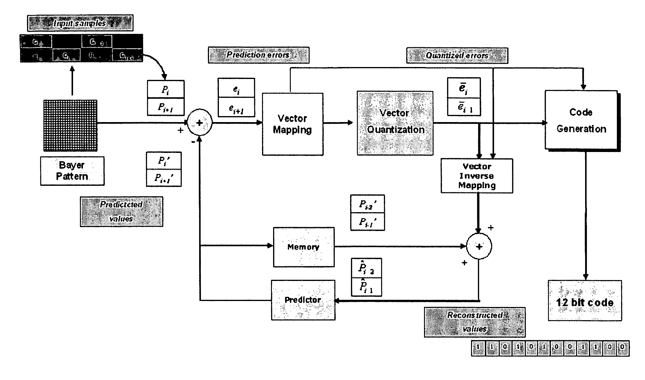
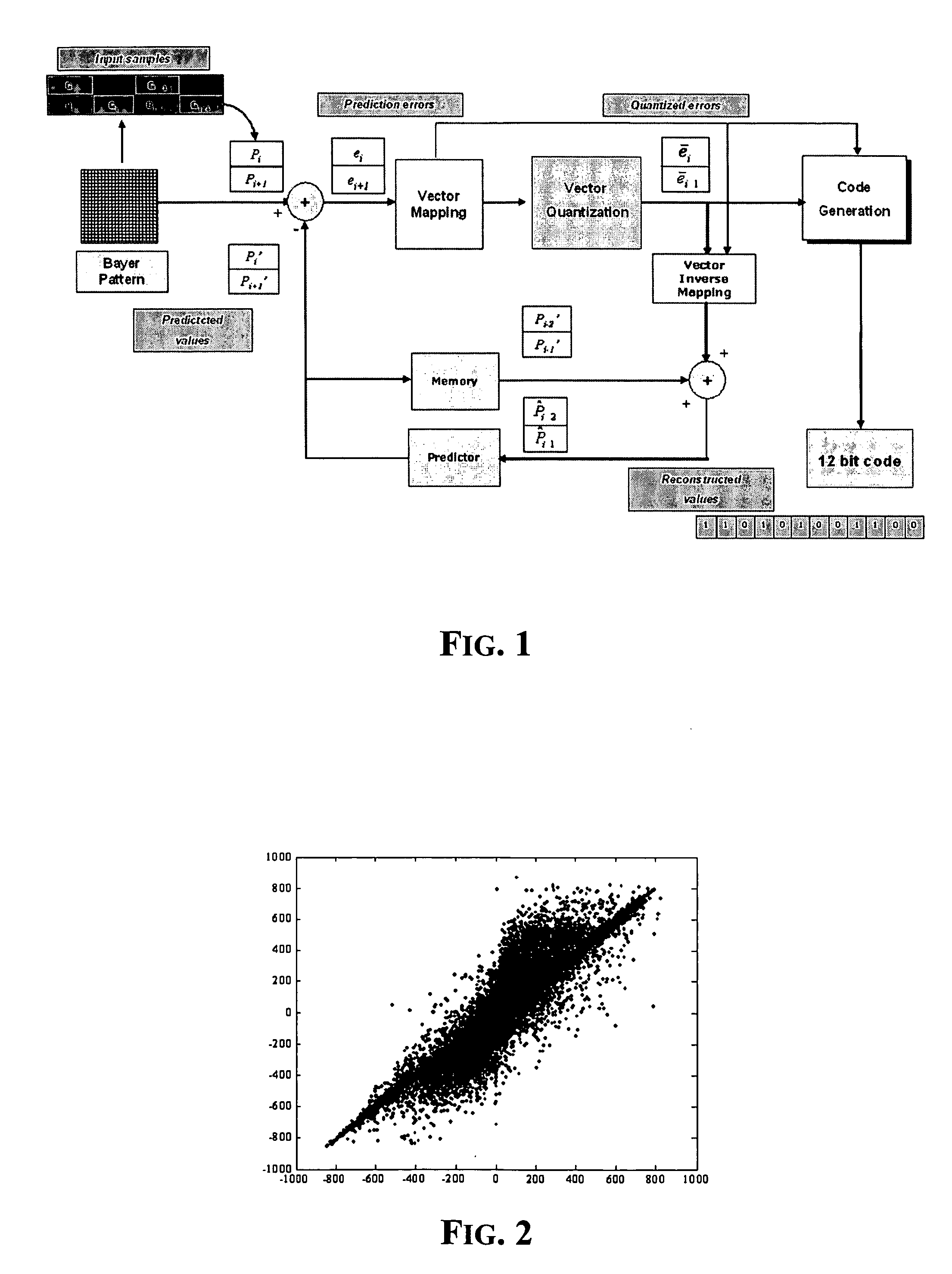
[0034] The source data is organized according to a Bayer color filter array (CFA) or briefly to a Bayer pattern, and the data sequences to be separately encoded are the pixel values belonging to each one of the three basic colors channels (R,G,B). FIG. 1 illustrates the method of DPCM+VQ compression process, according to this invention.

DPCM:

[0035] As depicted in the approach of FIG. 1, the input Bayer data are scanned line by line. The values Pi and Pi+1 (that are two successive pixels the same color channel of the Bayer image) are gathered in pairs (or couples) and for each so defined current input vector Pi, Pi+1, prediction values, Pi′, Pi+1′ are generated to calculate the differences or prediction errors ei, ei+1 that define what is called the predictor vector of the current vector. The DPCM step that precedes the VQ step exploits the high spatial correlation among adjacent pixels, to perform compression by coding just the new information between adjacent pels. In particular,...


PUM


Abstract

For each color channel, the process includes gathering Bayer pattern pixel values by pairs, each pair being composed by two successive pixels belonging to the channel along the scanning direction of the pixels of the image, thus each pair of values representing a current input vector, and calculating a predictor vector of the input vector in terms of the differences between the values defining the input vector and a pair of prediction values generated according to a certain criterion, for representing a prediction error. The process further includes quantizing each so calculated predictor vector according to a heavier or lighter degree of quantization depending on whether the predictor vector is representative of an area of relatively uniform color of the image or of an area of relatively abrupt changes of colors of the image, and generating a multibit code representative of the quantized predictor vector of the input vector according to a certain compression ratio.

Description

FIELD OF THE INVENTION [0001] The present invention relates to image acquisition and image data processing methods and devices. More particularly, the invention relates to a pipeline for generating a high quality color image by carrying out interpolation of chrominance data of pixel data coming from an image sensor for outputting interpolated image pixel data. BACKGROUND OF THE INVENTION [0002] Generally, when using a video camera or a digital still camera to photograph a color image, the incident light passes through filters for extracting certain wavelength components such as the basic color components R (red), G (green) and B (blue). In two-dimensional imaging, the imaging unit is composed of many pixels arranged in the vertical and horizontal directions. Each pixel of the two-dimensional image contain either red, green or blue color light because of the filtering of the incident light. A color sensing array of this type is disclosed in the document U.S. Pat. No. 3,971,065 (B. E....

Claims


Application Information

Patent Timeline
IPC IPC(8): H04B1/66H04N11/02H04N11/04H04N7/12H04N7/26H04N7/36H04N19/593H04N19/94
CPCH04N19/176H04N19/119H04N19/51H04N19/94H04N19/136H04N19/17H04N19/124
Inventor VELLA, FILIPPOBRUNA, ARCANGELO RANIERIBUEMI, ANTONIO VINCENZO
Owner STMICROELECTRONICS SRL
Why Eureka
Try Eureka