
Steel superior in machinability and method of production of same

a technology of machinability and steel, applied in the field of steel, can solve the problems of reducing precision, reducing tool life, and reducing tool life, and achieve the effect of improving both tool life and surface roughness

Inactive Publication Date: 2006-01-19
NIPPON STEEL CORP
View PDF1 Cites 8 Cited by
  • Summary
  • Abstract
  • Description
  • Claims
  • Application Information

AI Technical Summary

Benefits of technology

[0009] The present invention provides steel having a good surface roughness and a method of production of the same which avoid problems in hot rolling and hot forging while improving both the tool life and surface roughness and giving a machinability at least equivalent to that of conventional low carbon and lead free-machining steel.

Problems solved by technology

However, some users sometimes avoid use of Pb due to its environmental burden.
However, with addition of a large amount of S, if just making the MnS coarser, not only is it necessary to obtain an MnS distribution efficient for improving the machinability, but these form starting points of fracture in rolling, forging, etc. and cause many problems in production.
Further, in sulfur free-machining steel based on SUM23, the built-up edges easily form causing relief shapes at the cut surface and deterioration of the surface roughness accompanied with detachment of the built-up edges and breakoff of chips.
Therefore, from the viewpoint of the machinability as well, there is the problem of a drop in precision due to the deterioration of the surface roughness.
In chip disposal as well, it is considered better that the chips be able to be broken short, but with just simple addition of S, the ductility of the matrix is large, so sufficient breakage is not possible and no major improvement can be obtained.
Further, not much can be expected in view of the ingredients as well.
On the other hand, cutting tool life tends to be focused on since it has a direct effect on the production efficiency etc., but even in machinability, surface roughness is high in technical difficulty.
Surface roughness is affected by the inherent properties of the cut material, so it was difficult to obtain a surface roughness equal to or greater than that of conventional steel.
The surface roughness is directly linked with the performance of the part, so deterioration of the surface roughness becomes a cause of decline in part performance or an increase in the defect rate at the time of product production and is often stressed more than tool life.
However, even with these techniques, it is difficult to obtain a surface roughness equal to or better than that of conventional lead free-machining steel.
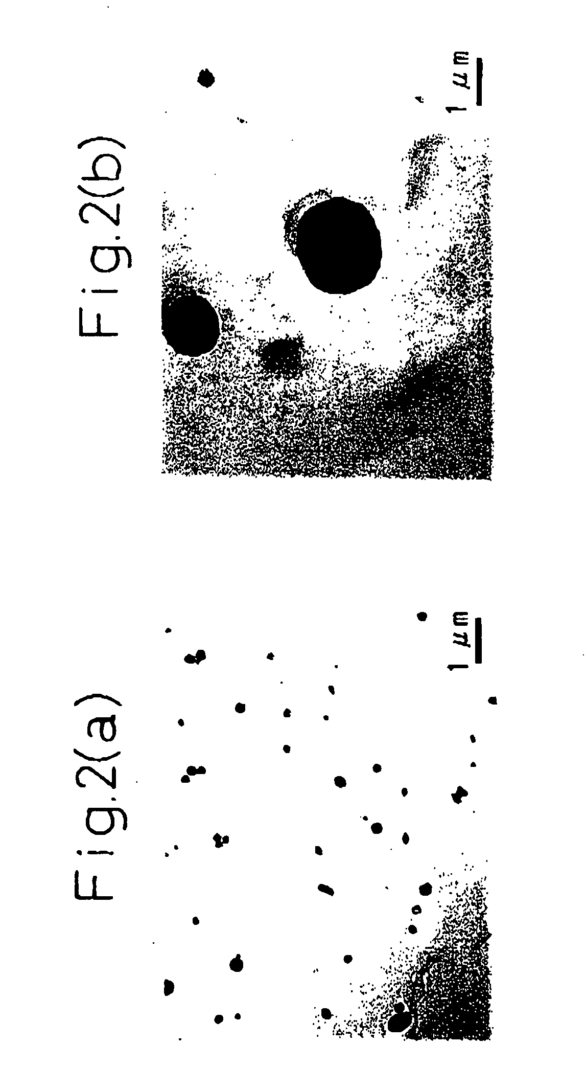
The reason is believed to be that the level of fine dispersion of inclusions defined in these only concerns grains of an average size of 3 μm or so, so homogeneous dispersion is insufficient and therefore built-up edges easily are formed and the surface roughness cannot be improved as much as that of conventional lead free-machining steel.

Method used


Image

  • Steel superior in machinability and method of production of same
  • Steel superior in machinability and method of production of same
  • Steel superior in machinability and method of production of same

Examples


example 1

[0132] The effect of the present invention will be explained by examples. Among the test materials shown in Table 1, Table 2 (continuation 1 of Table 1), Table 3 (continuation 2 of Table 1), Table 4 (continuation 3 of Table 1), Table 5 (continuation 4 of Table 1), and Table 6 (continuation 5 of Table 1), No. 13 was melted in a 270 t converter, while the rest were melted in a 2 t vacuum melting furnace, then the materials were bloomed into billets and rolled to φ60 mm.

[0133] In the section on heat treatment in the tables, the examples marked as “Normal.” are held at 920° C. for at least 10 min and then air-cooled. The examples of the invention marked as “QT” are inserted into a water tank at the rear end of the rolling line and rapidly cooled from 920° C., then held by annealing at 700° C. for at least 1 hour. The pearlite area ratio was adjusted by this. In the invention examples, steels with a low amount of C can be reduced in area ratio of pearlite even with normalization.

[0134]...

example 2

[0148] Parts of the test materials shown in Table 9, Table 10 (continuation 1 of Table 9), Table 11 (continuation 2 of Table 9), Table 12 (continuation 3 of Table 9), Table 13 (continuation 4 of Table 9), and Table 14 (continuation 5 of Table 9) were produced by a 270 t converter, then casted at a cooling rate of 10 to 100° C. / min. The billet was bloomed, then further rolled to φ50 mm. Further, the rest was melted in a 2 t vacuum melting furnace and rolled to φ50 mm. At this time, the cooling rate of the billet was adjusted by changing the cross-sectional dimensions of the casting mold. The machinability of the material was evaluated by a drilling test of the conditions shown in Table 7 and plunge cutting of the conditions shown in Table 8. The drill boring test is a method evaluating the machinability by the maximum cutting speed (so-called VL1000, unit m / min) enabling cutting up to a cumulative hole depth of 1000 mm. Plunge cutting is a method of evaluating the surface roughness b...


PUM

PropertyMeasurementUnit
Temperatureaaaaaaaaaa
Lengthaaaaaaaaaa

Abstract

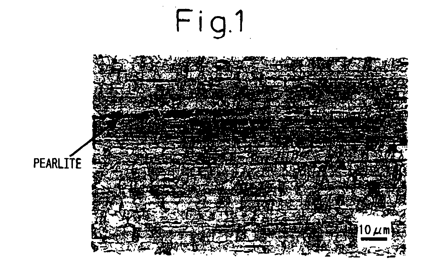
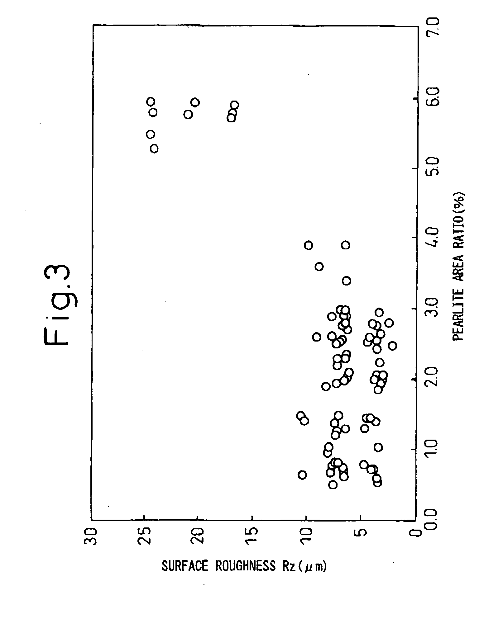
The present invention provides steel superior in machinability comprised of, by wt %, C: 0.005 to 0.2%, Si: 0.001 to 0.5%, Mn: 0.2 to 3.0%, P: 0.001 to 0.2%, S: 0.03 to 1.0%, T.N: 0.002 to 0.02%, T.O: 0.0005 to 0.035%, and the balance of Fe and unavoidable impurities, said steel satisfying one or both of Mn / S in the steel being 1.2 to 2.8 or an area ratio of pearlite over a grain size of 1 μm in a microstructure of the steel being not more than 5%.

Description

TECHNICAL FIELD [0001] The present invention relates to steel used for automobiles, general machinery, etc. and a method of production of the same, more particularly relates to steel superior in machinability which is superior in tool life and cut surface roughness at the time of cutting and chip disposal and a method of production of the same. BACKGROUND ART [0002] General machinery and automobiles are produced by assembling large numbers of parts. From the viewpoint of the precision requirements and production efficiency, the parts are in many cases produced through a cutting process. At this time, reduction of costs and improvement of production efficiency are required improvement of the machinability of the steel is also sought. In particular, conventional SUM23 and SUM24 have been developed stressing machinability. Up to now, it has been known that to improve the machinability, addition of S, Pb, or another machinability improving element is effective. However, some users somet...

Claims


Application Information

Patent Timeline
IPC IPC(8): C22C38/04C21D8/00C22C38/00C22C38/60
CPCC21D2211/005C21D2211/009C22C38/60C22C38/002C22C38/04C22C38/001
Inventor HASHIMURA, MASAYUKIMIZUNO, ATSUSHINAITO, KENICHIROHAGIWARA, HIROSHIISOBE, KOHICHIHIRATA, HIROSHI
Owner NIPPON STEEL CORP
Learn More