Device for correcting reference position for transfer mechanism, and correction method

a reference position and correction method technology, applied in the field of devices, can solve the problems of error caused by a resolution of an encoder and member error, and achieve the effect of simple structure and effective solving

Inactive Publication Date: 2006-01-19
TOKYO ELECTRON LTD +1
View PDF2 Cites 12 Cited by
  • Summary
  • Abstract
  • Description
  • Claims
  • Application Information

AI Technical Summary

Benefits of technology

[0011] The present invention has been made in view of the above difficulties so as to effectively solve the same. An object of the present invention is to provide a reference position correcting device having a simple structure and a reference position correcting method for a conveying mechanism, in which reference positions in all the X, Z, θ, and R directions can be corrected with one sensing light beam.

Problems solved by technology

When the system is fabricated or drastically remodeled, errors such as a process error and an assembly error of members, and an error caused by a resolution of an encoder inevitably occur.

Method used


Image

  • Device for correcting reference position for transfer mechanism, and correction method
  • Device for correcting reference position for transfer mechanism, and correction method
  • Device for correcting reference position for transfer mechanism, and correction method

Examples


first embodiment

[0037] Referring to FIGS. 1 to 10, a treatment system including a reference position correcting device for a conveying mechanism in the present invention is described below.

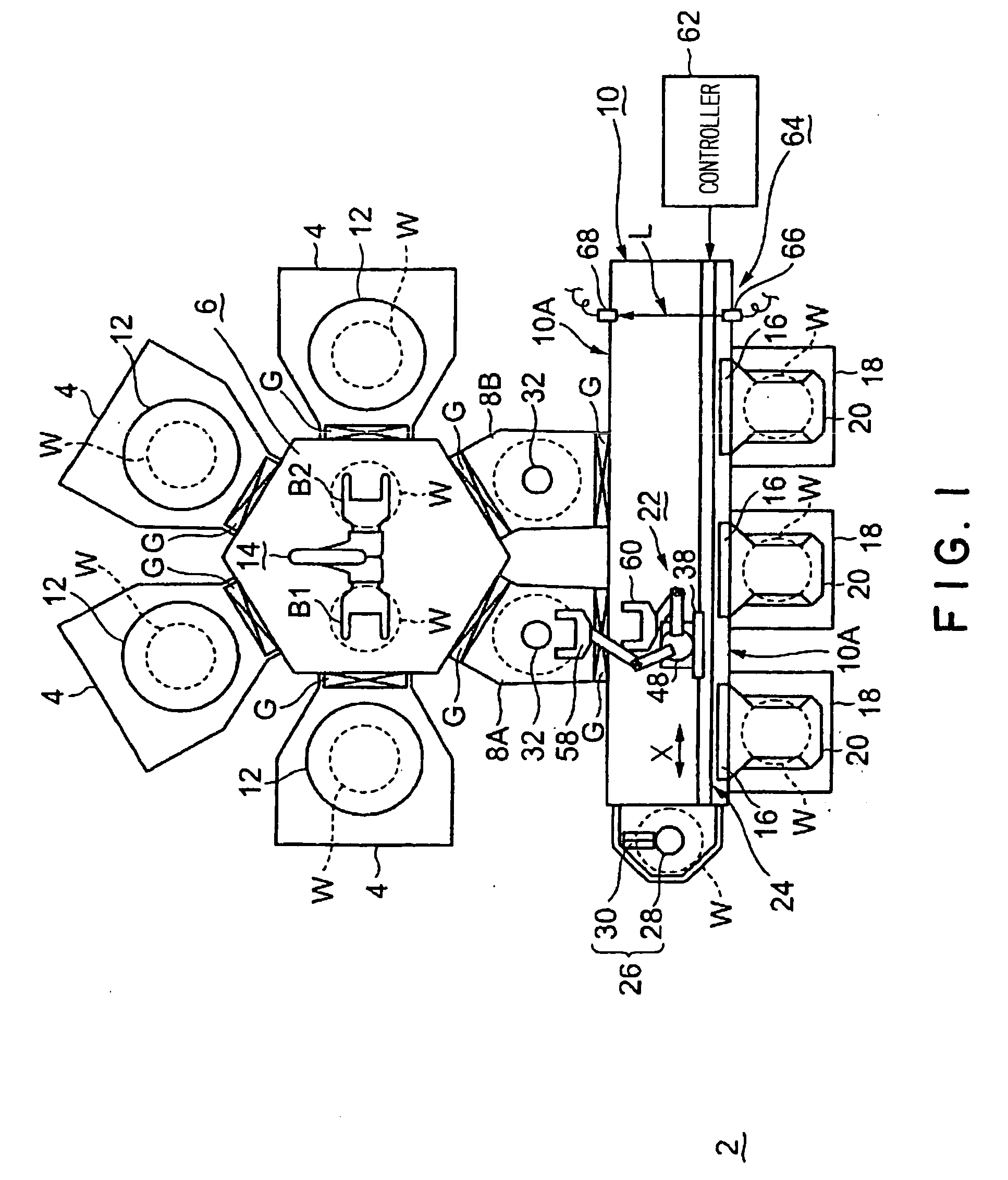
[0038] As shown in FIG. 1, a treatment system 2 includes four treatment vessels 4, a hexagonal common conveying vessel 6, a first load lock vessel 8A, a second load lock vessel 8B, and an elongated inlet-side conveying vessel 10.

[0039] To be specific, the treatment vessels 4 are connected to four side surfaces of the common conveying vessel 6, while the first and the second load lock vessels 8A and 8B are connected to the rest two side surfaces of the common conveying vessel 6. The inlet-side conveying vessel 10 is commonly connected to the first and the second load lock vessel 8A and 8B. A first conveying mechanism 22 is disposed in the inlet-side conveying vessel 10.

[0040] The common conveying vessel 6 and each of the four treatment vessels 4 are connected through a gate valve G which can air-tightly close a ...

second embodiment

[0095] As shown in FIGS. 11 to 13, a conveying mechanism 80 in the second embodiment includes a cylindrical table 82. The table 82 is secured on the base 44 (FIG. 2) which can move in the Z direction, for example. Two arm mechanisms 84 and 86 are disposed on the table 82, which have coaxial turning shafts and coaxial connecting shafts. Picks 88 and 90 for holding a wafer are attached on distal ends of the respective arm mechanisms 84 and 86.

[0096] The arm mechanisms 84 and 86 include a common first arm 92, and second arms 94 and 96. A proximal end of the first arm 92 is attached on a center of the table 82, such that the first arm 92 can turn in the horizontal plane. The second arms 94 and 96 are connected to a distal end of the first arm 92 in a vertical arrangement. The second arms 94 and 96 can rotate independently from each other in the horizontal plane relative to the first arm 92. The one pick 88 is attached to a distal end of the upper second arm 96. The other pick 90 is atta...


PUM


Abstract

A conveying mechanism (22) is disposed in a conveying vessel (10). The conveying mechanism includes: a moving member (38) which can move in a horizontal moving direction; a rotary table (48) attached to the moving member such that the rotary table can turn in a horizontal turning direction and move in the vertical direction; and two arm mechanisms which can bend and stretch in a horizontal operating direction relative to the rotary table. A reference position correcting device for the conveying mechanism includes: a light emitter (66) for emitting a sensing light beam (L); a light detector (68) for receiving the sensing light beam; and correcting means (62). The light emitter and the light detector are fixedly positioned on the conveying vessel. The correcting means corrects reference positions of the rotary table in the moving, vertical, and turning directions, and corrects a reference position of each of the arm mechanisms in the operating direction, based on a detection by the light detector about a light-transmitting state and a light-shielding state of the sensing light beam switched in compliance with the movement and the turn of the rotary table. A light-shielding member is attached on the rotary table, for switching the sensing light beam between the light-transmitting state and the light-shielding state, in compliance with the movement and the turn of the rotary table.

Description

TECHNICAL FIELD [0001] The present invention relates to a device and a method of correcting reference positions of a conveying mechanism relative to various operational directions, the conveying mechanism being used in a treatment system for a semiconductor wafer or the like. BACKGROUND ART [0002] In order to manufacture a semiconductor integrated circuit, a wafer is generally subjected to various treatments such as film-forming, etching, oxidation, and diffusion treatments. In connection with a finer, higher integration of a semiconductor integrated circuit, a so-called clustered treatment system has been introduced to improve a throughput and a yield. Such a clustered system includes a plurality of treatment apparatuses for carrying out the same or different treatments, the apparatuses being connected to each other through a common conveying vessel. Thus, wafers can be continuously subjected to various treatments, without being exposed to an atmosphere. [0003] In this type of trea...

Claims


Application Information

Patent Timeline
Patent Type & Authority Applications(United States)
IPC IPC(8): G01P21/00G01B11/00B25J9/16B25J13/08B25J19/02B62D57/032G01B11/26H01L21/677H01L21/68
CPCB25J9/1692B25J19/021H01L21/681H01L21/67766B62D57/032H01L21/68
Inventor SAEKI, HIROAKIKAMIGAKI, TOSHIO
Owner TOKYO ELECTRON LTD
Why Eureka
Try Eureka