

Slitter apparatus and production method of electrode
Active Publication Date: 2006-01-26
TDK CORPARATION
View PDF1 Cites 16 Cited by
- Summary
- Abstract
- Description
- Claims
- Application Information
AI Technical Summary
Benefits of technology
[0018] The present invention has been accomplished in view of the problems in the conventional technology, and an object of the present invention is to provide a slitter apparatus capable of adequately suppressing the adhesion of chips of the collector to the side faces of the upper blade and adequately suppressing the production of burrs at the cut surfaces of the collector, during the cutting of the sheetlike electrode. Another object of the present invention is to provide an electrode production method using the foregoing slitter apparatus.
[0024] In the slitter apparatus of the present invention, the hardnesses of the upper blades and lower blades are in the range of 6.9×10³ to 8.8×10³ N / mm2 (approximately 700 to approximately 900 kgf / mm2). Fine burrs and chips produced in the collector during the cutting tend to be tangled with the edge faces on crossing surfaces between the upper blades and the lower blades. When the upper blades and the lower blades have their respective hardnesses in the above range, it is feasible to adequately suppress occurrence of fine deformation in the upper blades and the lower blades, and it is thus feasible to make very small a space (relief space) which the burrs and chips can enter between the upper blades and the lower blades. For this reason, it is feasible to reduce the burrs moving along the edge faces and remaining on the collector, and the chips adhering to the edge faces.
[0028] Since the upper blades and the lower blades have the aforementioned hardnesses and surface roughnesses while keeping the difference of not more than 4.9×10² N / mm2 (50 kgf / mm2) between the hardnesses of the upper blades and the lower blades and the difference of not more than 2 μm between the surface roughnesses, it is feasible to prevent abrasion of the edge faces at engagement portions between the upper blades and the lower blades. Since it becomes feasible to prevent the abrasion between the edge faces, the present invention can further enhance the effect of preventing the production of chips and the adhesion thereof to the edge faces. Therefore, the slitter apparatus of the present invention is able to adequately suppress the adhesion of chips of the collector to the edge faces and to adequately suppress the production of burrs at the cut surfaces of the collector, during the cutting of the sheetlike electrode. Furthermore, since the adhesion of chips to the edge faces is well suppressed in the slitter apparatus of the present invention, it is feasible to increase the life of the upper blades and the lower blades.
[0030] Since the electrode production method involves the step of cutting the sheetlike electrode with the slitter apparatus of the present invention as described above, it can adequately suppress the production of burrs in the collector. Therefore, the electrode production method of the present invention permits us to obtain the electrode that can adequately suppress occurrence of an internal short circuit due to the burrs of the collector, when used in fabrication of an electrochemical device.
Problems solved by technology
For this reason, when the conventional slitter apparatus with the upper blades of the shear method or the gang method is used to cut the sheetlike electrode, there arises a problem that burrs of the collector are likely to be made at cut surfaces.
A conceivable reason for it is that the cutting load from the cutting edge is scattered because of the existence of the active-material-containing layer formed on the collector, so as to result in failing to concentrate the shear force on the collector, this results in stretching the collector of metal, and burrs are produced when the collector is cut in this state.
A large burr projecting above the active-material-containing layer of the anode can break a separator and cause a trouble such as a short circuit between the anode and cathode inside the battery.
In addition, the copper powder attached to the anode surface or to the edge part of the anode could also cause a similar trouble, and a cleaning step for removal of the copper powder used to be required after the cutting with the slitter apparatus.
This resulted in complicating the electrode production steps and posing the problem of increase of production cost.
However, where the above-described cutting apparatus with the upper blades was used in cutting the cathode with the collector of aluminum foil, it was difficult to adequately suppress production of burrs and adhesion of aluminum to the side faces of the upper blades.
In the case of electric double layer capacitors among the electrochemical devices, aluminum foil is often used for the collector in the both anode and cathode, and thus the above problem more prominently affects characteristics of the electric double layer capacitors.
In the case of scraping off the burrs from the periphery of the substrate after the cutting, a pointed chip, and the active material scraped off together with the substrate sometimes attached to the electrode surface, and caused an internal short circuit.
However, this method is also the method that covers the cut end faces with the resin after the cutting, but not one that suppresses the production of pointed burrs and chips.
Therefore, there were cases where burrs or the like once forced down agin stood up thereafter to penetrate the separator, and it was difficult to adequately prevent occurrence of the internal short circuit.
Method used
View moreImage
Smart ImageViewing Examples

Examples
examples
[0076] The present invention will be more specifically described on the basis of Examples and Comparative Examples, but it is noted that the present invention is by no means limited to the examples below.
Login to View More PUM
| Property | Measurement | Unit |
|---|---|---|
| Length | aaaaa | aaaaa |
| Length | aaaaa | aaaaa |
| Length | aaaaa | aaaaa |
Abstract
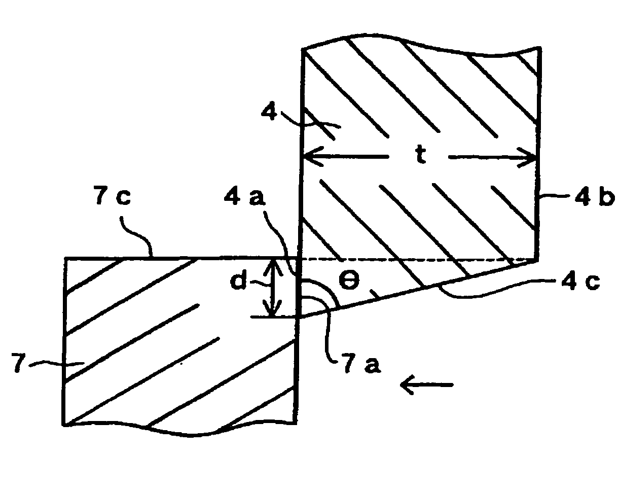
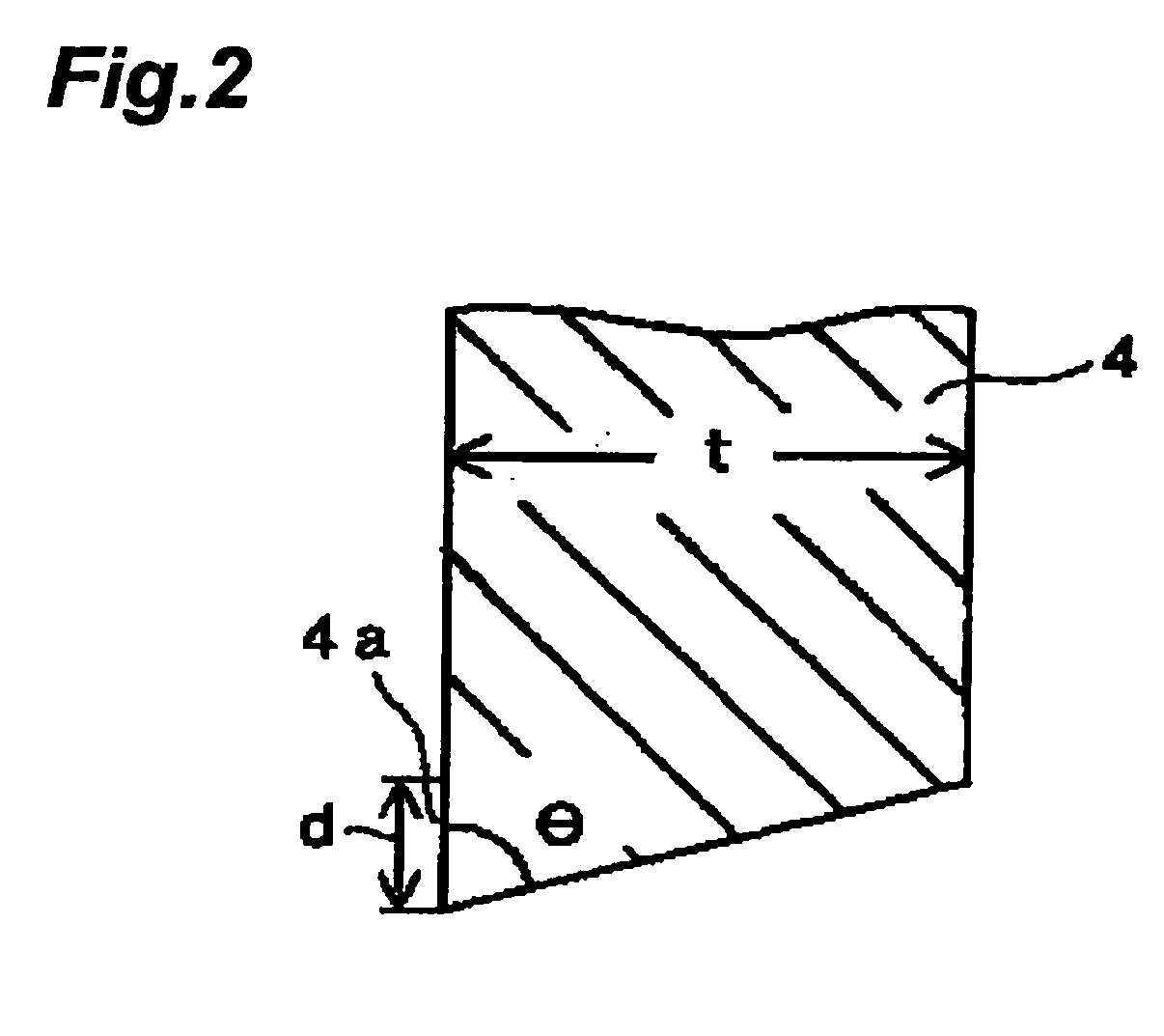
A slitter apparatus has a rotary shaft provided with one or more upper blades, and a rotary shaft provided with one or more lower blades, the rotary shafts being arranged in parallel with each other and at such a spacing as to achieve a predetermined engagement depth with contact between side face of peripheral part of upper blades and side face of peripheral part of lower blades, wherein a thickness of upper blades is not less than 1 mm, an included angle of upper blades is in a range of 75 to 88°, hardnesses of upper blades and lower blades are in a range of 6.9×10³ to 8.8×10³ N / mm2, a difference between the hardness of upper blades and the hardness of lower blades is not more than 4.9×10² N / mm2, surface roughnesses of upper blades and lower blades are not more than 4 μm, and a difference between the surface roughness of upper blades and the surface roughness of lower blades is not more than 2 μm.
Description
BACKGROUND OF THE INVENTION [0001] 1. Field of the Invention [0002] The present invention relates to a slitter apparatus for slitting a sheetlike object in a predetermined width, and a method of producing an electrode with the same. [0003] 2. Related Background Art [0004] With recent reduction in size and weight of electronic devices such as various office automation equipment, VTR cameras, and cell phones, there are demands for reduction in size and weight and for enhancement of performance of electrochemical devices such as secondary batteries and electrochemical capacitors used as drive power sources for these electronic devices. [0005] Electrodes of the electrochemical devices are normally produced as follows: an electrode active material is mixed with a binder to prepare a coating solution for formation of electrodes, this coating solution is applied onto one surface or both surfaces of a collector, the coating solution is dried to form an active-material-containing layer on on...
Claims
Login to View More Application Information
Patent Timeline
 IPC IPC(8): B26D1/00B26D1/20B26D1/24H01M4/139
CPCB26D1/0006B26D1/225B26D1/245B26D2001/002Y02E60/122B26D2001/0053B26D2007/0075H01M4/04H01M4/0404B26D2001/0046Y02E60/10Y10T83/04Y10T83/4757Y10T83/4778
InventorKATAI, KAZUOMIYAKI, YOUSUKEENDO, SEIICHI
OwnerTDK CORPARATION