Aluminum oxide and aluminum oxynitride layers for use with phosphors for electroluminescent displays

a technology of aluminum oxide and phosphor, which is applied in the direction of luminescent compositions, discharge tubes/lamp details, discharge tubes luminescent compositions, etc., can solve the problems of reducing the efficiency with which electrons interact with the activator species in the phosphor material to emit light, reducing the efficiency by which the light generated in the phosphor is transmitted from the device to provide useful luminance, and not considering providing aluminum oxide or aluminum oxynitride layers. to achiev

Inactive Publication Date: 2006-01-26
SANYO ELECTRIC CO LTD +1
View PDF39 Cites 14 Cited by
  • Summary
  • Abstract
  • Description
  • Claims
  • Application Information

AI Technical Summary

Benefits of technology

[0008] The present invention is a thin film alkaline earth thioaluminate phosphor doped with a rare earth activator species that has an improved operating life. The improved operating life is achieved by providing an aluminum oxide or aluminum oxynitride layer directly in contact with the bottom portion of the phosphor. The aluminum oxide or aluminum oxynitride layer is therefore positioned between the thick dielectric structure of the display and the phosphor layer so that it is in contact with the phosphor layer.
[0009] The aluminum oxide or aluminum oxynitride layer improves the luminance and operating life of the phosphor by acting as a barrier to chemical species that may cause a reduction in the realizable luminance of the phosphor material by causing a reduction in the efficiency with which electrons are injected into the phosphor film during operation of the device. This causes a reduction in the efficiency with which electrons interact with the activator species in the phosphor material to emit light, or reduces the efficiency by which light generated in the phosphor is transmitted from the device to provide useful luminance. The prior art has not contemplated providing an aluminum oxide or aluminum oxynitridelayer directly adjacent a lower surface of the phosphor that is between the phosphor and a thick film dielectric layer in an electroluminescent device.

Problems solved by technology

This causes a reduction in the efficiency with which electrons interact with the activator species in the phosphor material to emit light, or reduces the efficiency by which light generated in the phosphor is transmitted from the device to provide useful luminance.
The prior art has not contemplated providing an aluminum oxide or aluminum oxynitridelayer directly adjacent a lower surface of the phosphor that is between the phosphor and a thick film dielectric layer in an electroluminescent device.

Method used


Image

  • Aluminum oxide and aluminum oxynitride layers for use with phosphors for electroluminescent displays
  • Aluminum oxide and aluminum oxynitride layers for use with phosphors for electroluminescent displays
  • Aluminum oxide and aluminum oxynitride layers for use with phosphors for electroluminescent displays

Examples


example 1

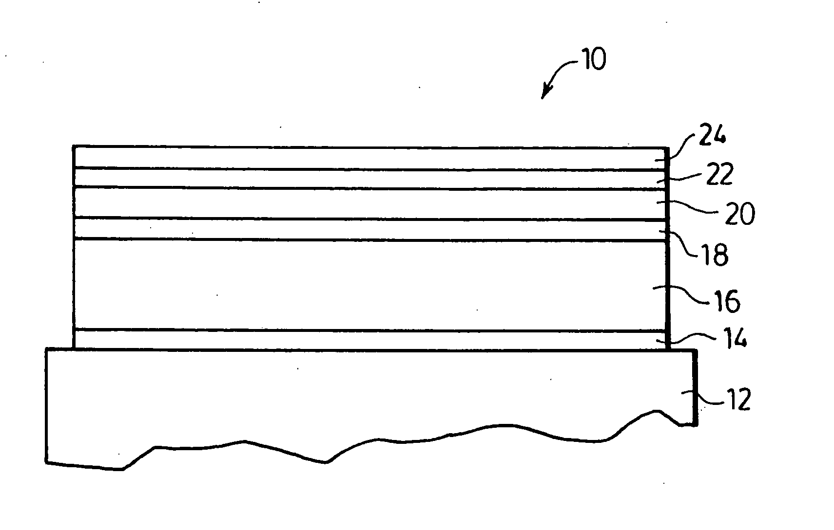
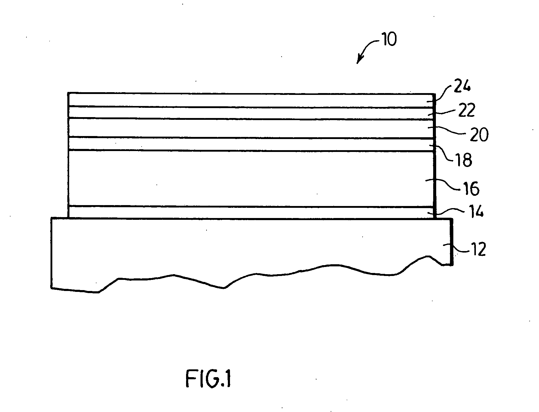
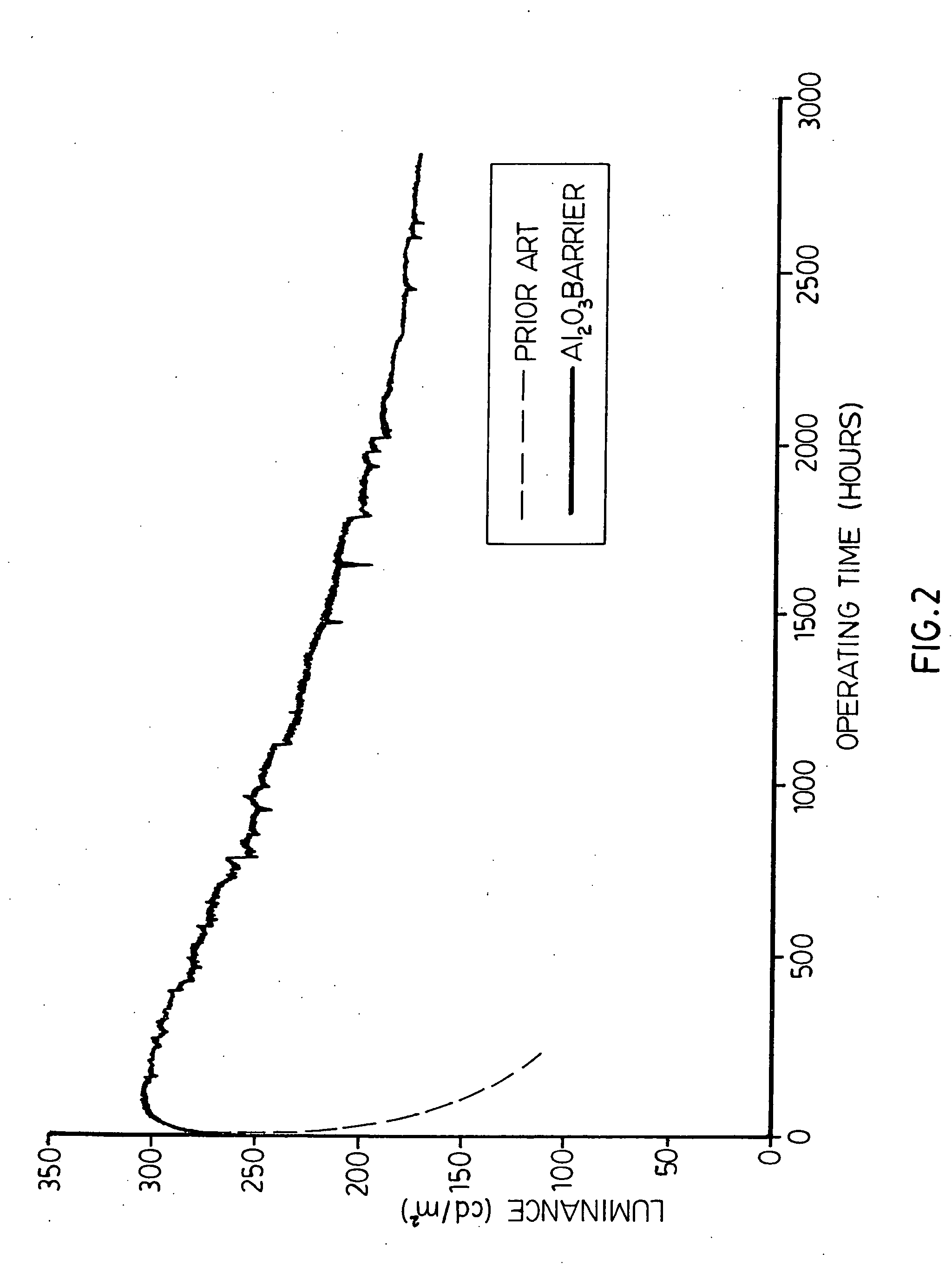
[0051] This example serves to illustrate the performance and operating stability of devices of the prior art. A thick dielectric electroluminescent device incorporating thin film phosphor layers comprising barium thioaluminate activated with europium was constructed. The thick film substrate was comprised of a 5 cm by 5 cm glass having a thickness of 0.1 cm. A gold electrode was deposited on the substrate, followed with a lead magnesium niobate-titanate thick film high dielectric constant dielectric layer and a PZT smoothing layer in accordance with the methods exemplified in Applicant's co-pending international application PCT CA00 / 00561 filed May 12, 2000 (the disclosure of which is incorporated by reference herein in its entirety). A thin film dielectric layer of barium titanate, with a thickness of about 120 nanometers, was deposited in accordance with the methods exemplified in the Applicant's U.S. Pat. No. 6,589,674 (the disclosure of which is incorporated by reference herein ...

example 2

[0054] This example serves to illustrate the performance and operating stability of devices of the invention in comparison to that of the prior art of example 1. A device was constructed similar to that of example 1, except that an aluminum oxide layer was deposited on the barium tantalate layer prior to phosphor deposition. The luminance data for this device is also shown in FIG. 2 and shows an initial luminance of about 220 candelas per square meter followed by an increase in luminance during the initial hours of operation, followed by a gradual loss of luminance. The luminance after 2800 hours of operation was still about 140 candelas per square meter.

example 3

[0055] This example serves to show the effect of various layers in a thick dielectric electroluminescent devices in inhibiting migration of oxygen into the phosphor film and in improving the performance and stability of the devices with the use of the present invention.

[0056] Four devices were constructed, the first and second of which were similar to the devices of examples 1 and 2 respectively, the third of which was similar to that of example 1 except that it did not have the barium tantalate layer and the fourth of which was similar to that of example 2 except that it did not have the barium tantalate layer. Electron Spectroscopy for Chemical Analysis (ESCA) was used to measure the concentration of chemical species with depth in the devices. In particular, the ratio of oxygen to titanium in the PZT smoothing layer was determined to give a measure of changes in the oxygen concentration in the PZT layer. The oxygen to titanium ratio was 9.2±0.3 for the first device which is the p...


PUM

PropertyMeasurementUnit
thicknessaaaaaaaaaa
pressureaaaaaaaaaa
thicknessaaaaaaaaaa

Abstract

A novel laminate is provided to improve the operating stability of thioaluminate based phosphors used in ac thick film dielectric electroluminescent displays. The novel structure comprises a rare earth activated alkaline earth thioaluminate phosphor thin film layer and an aluminum oxide or aluminum oxynitride layer provided directly adjacent and in contact with the bottom of the phosphor thin film layer. The invention is particularly applicable to phosphors used in electroluminescent displays that employ thick dielectric layers subject to high processing temperatures to form and activate the phosphor films.

Description

FIELD OF THE INVENTION [0001] The present invention relates to improving the operating stability of blue light-emitting phosphor materials used for full color ac electroluminescent displays employing thick film dielectric layers with a high dielectric constant. More specifically, the invention provides aluminum oxide or aluminum oxynitride layers in contact with the phosphor layer to prevent phosphor degradation. BACKGROUND OF THE INVENTION [0002] The thick film dielectric structure provides for superior resistance to dielectric breakdown as well as a reduced operating voltage as compared to thin film electroluminescent (TFEL) displays, as exemplified by U.S. Pat. No. 5,432,015. The thick film dielectric structure also enhances the amount of charge that can be injected in to the phosphor film to provide greater luminosity than can be realized from TFEL displays. Full colour thick dielectric electroluminescent displays are described for example in the Applicant's PCT CA03 / 01567. Thes...

Claims


Application Information

Patent Timeline
Patent Type & Authority Applications(United States)
IPC IPC(8): H05B33/00
CPCC09K11/7718C09K11/7731C09K11/7734H05B33/22H05B33/10H05B33/14C09K11/7786C09K11/64C09K11/77
Inventor XIN, YONGBAOYOSHIDA, ISAOACCHIONE, JOEHAMADA, HIROKI
Owner SANYO ELECTRIC CO LTD
Why Eureka
Try Eureka