Extreme ultraviolet reticle protection using gas flow thermophoresis

a technology of ultraviolet reticle and gas flow, which is applied in the direction of lighting and heating apparatus, instruments, printing, etc., can solve the problems of affecting the maintenance of the surface of different temperatures within the euv apparatus, pellicles are not used to protect euv reticles, and the lithography process which utilizes the reticle may be compromised, so as to reduce particle contamination and reduce particle contamination. the effect of the reticle contamination

Inactive Publication Date: 2006-01-26
NIKON CORP
View PDF10 Cites 27 Cited by
  • Summary
  • Abstract
  • Description
  • Claims
  • Application Information

AI Technical Summary

Benefits of technology

[0013] The present invention relates to using a flow of a relatively cool gas to establish a temperature gradient between a reticle and a reticle shield such that particle contamination on the reticle may be reduced. According to one aspect of the present invention, an apparatus that reduces particle contamination on a surface of an object includes a member having a surface proximate to the object, e.g., a plate, and a gas supply. The plate is arranged to be positioned in proximity to the object such that the plate, which is of a second temperature, and the object, which is of a first temperature, are substantially separated by a space. The gas supply supplies a gas flow to the space. The gas is of a third temperature that is lower than the first temperature and lower than the second temperature. Heat flow between the gas, the plate, and the object create a temperature gradient in the gas and, hence, a thermophoretic force that is suitable for conveying particles in the space away from the object.
[0015] Allowing a reticle and a nearby surface, e.g., a reticle shield, to remain at substantially the same temperature while allowing for thermophoretic effects to convey particles away from the reticle reduces particle contamination without causing relatively significant thermal distortion effects and performance issues. By maintaining a reticle and a nearby surface at substantially the same temperature while providing a cooled or chilled gas in a space between the reticle and the nearby surface, a temperature gradient may be created between the reticle and the nearby surface. The presence of the temperature gradient allows thermophoretic forces to convey particles away from both the reticle and the nearby surface. The source of the gas is local, and the gas may be locally filtered, so the likelihood of the gas sweeping additional particles into the vicinity of the reticle is quite small.
[0017] In one embodiment, the flow of the gas in the space creates a temperature gradient in the space that enables the flow of the gas to convey any particles in the space away from the surface of the object. In another embodiment, providing the flow of the gas in the space includes cooling the gas to the third temperature and controlling the amount of the gas that flows through the first opening.

Problems solved by technology

When a pattern is distorted, as for example due to particle contamination on a surface of a reticle, a lithography process which utilizes the reticle may be compromised.
Pellicles, however, are not used to protect EUV reticles, since thin films generally are not suitable for providing protection in the presence of EUV radiation.
While the positioning of a surface in proximity to a reticle that is cooler than the reticle reduces particle contamination of the reticle, maintaining surfaces of different temperatures within an EUV apparatus is often problematic.
For example, maintaining surfaces at different temperatures may complicate temperature control of critical systems.
In addition, issues relating to thermal expansion and distortion typically arise when a reticle and adjacent components are maintained at different temperatures.
When there is thermal expansion or distortion within an EUV apparatus, e.g., with respect to a reticle or a shield, the integrity of an overall lithography process or, more generally, a semiconductor fabrication process may be compromised.

Method used


Image

  • Extreme ultraviolet reticle protection using gas flow thermophoresis
  • Extreme ultraviolet reticle protection using gas flow thermophoresis
  • Extreme ultraviolet reticle protection using gas flow thermophoresis

Examples


Embodiment Construction

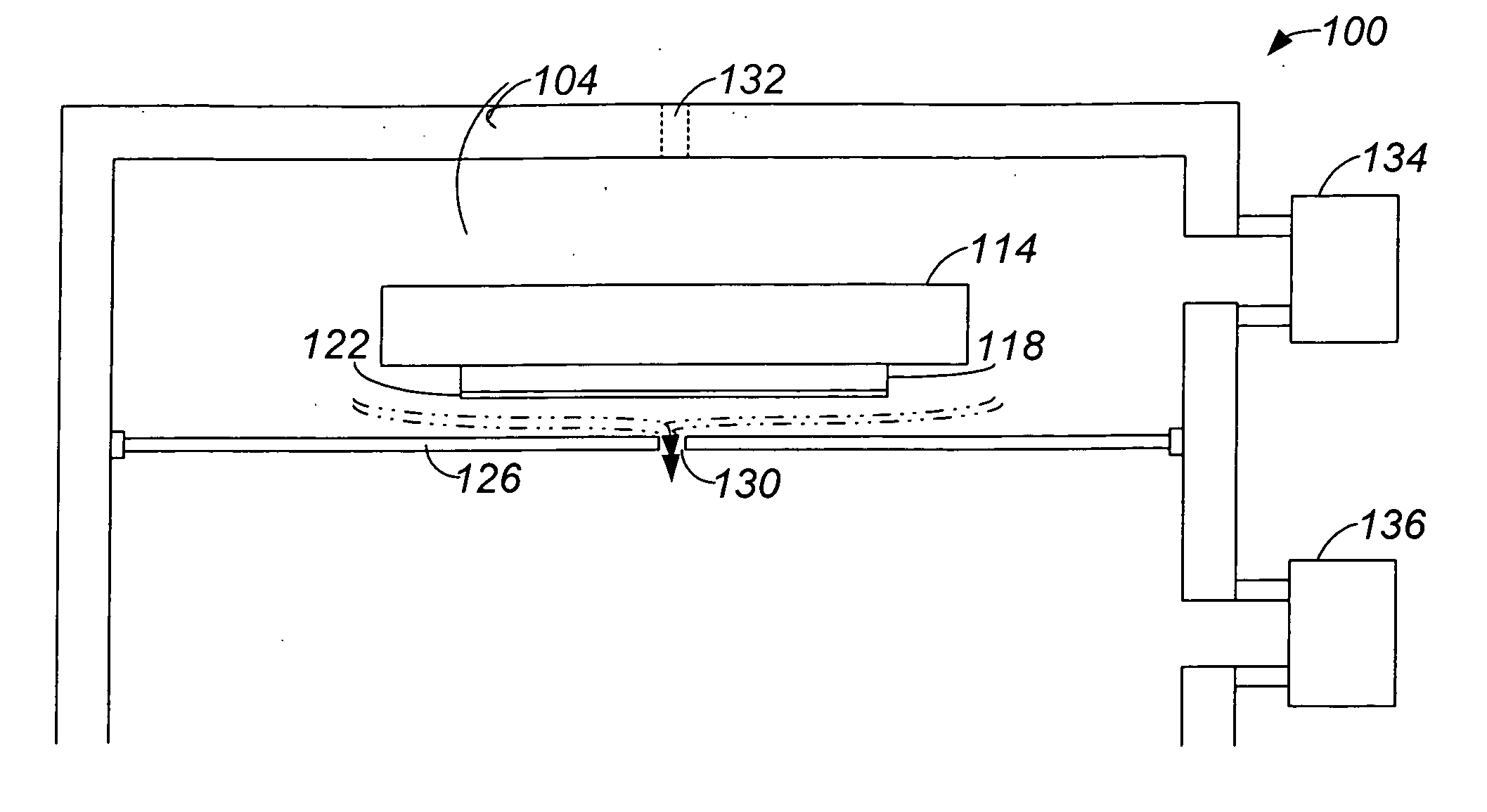
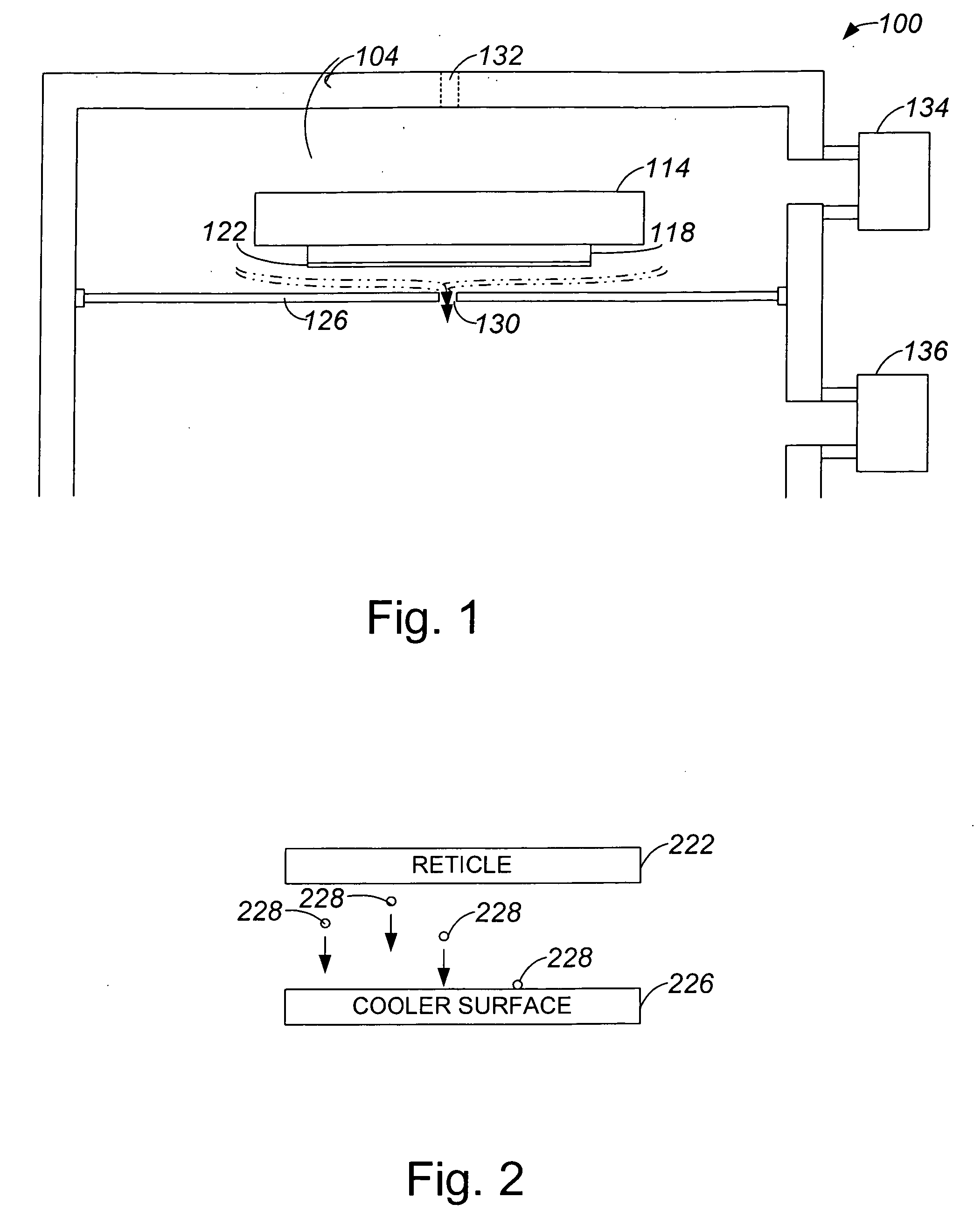
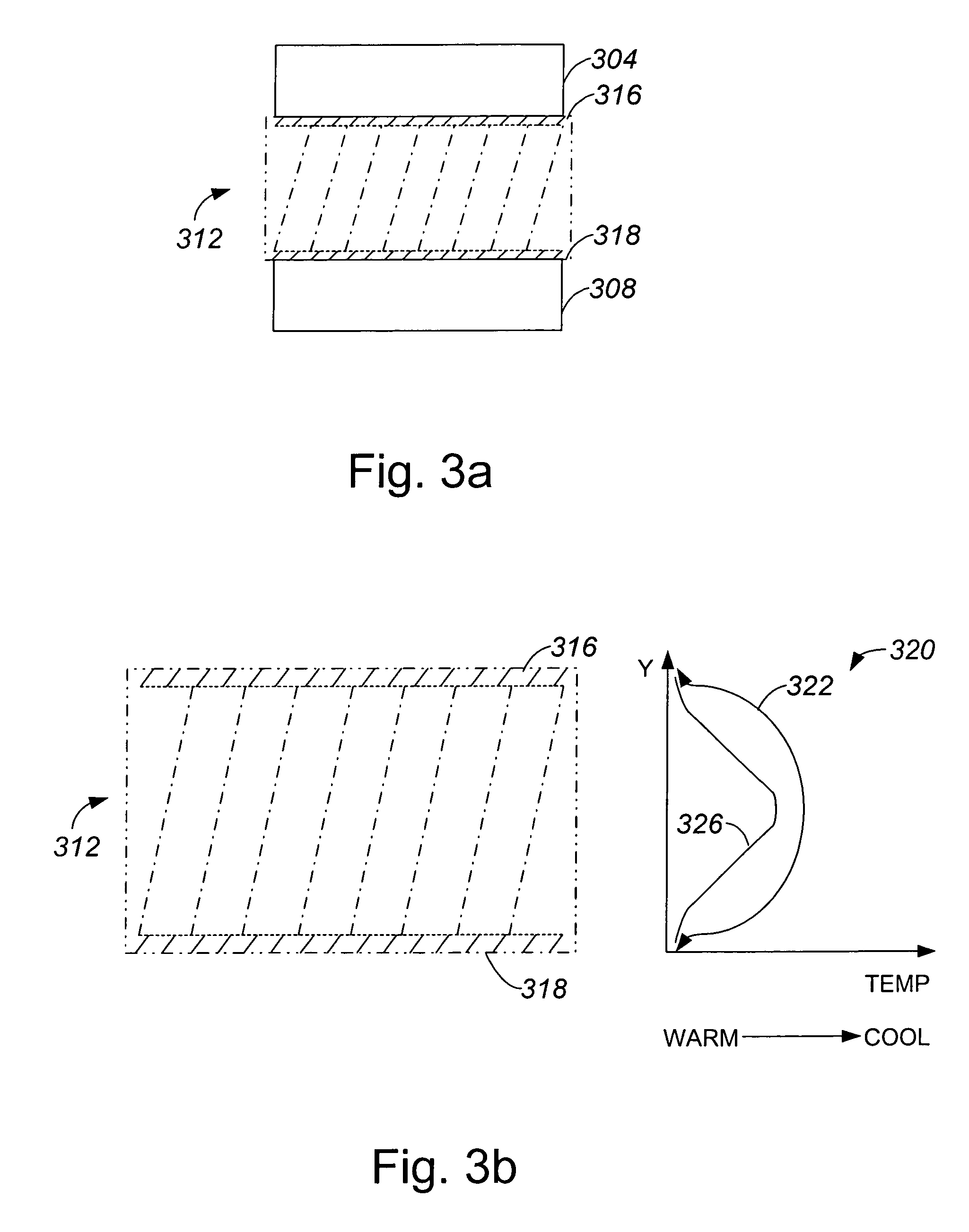
[0037] Particle contamination on critical surfaces of reticles such as reticles used in extreme ultraviolet (EUV) lithography systems may compromise the integrity of semiconductors created using the reticles. Hence, protecting critical surfaces of reticles from airborne contaminants is important to ensure the integrity of lithography processes. Some reticles are protected from airborne particles through the use of pellicles. However, pellicles are not suitable for use in protecting surfaces of EUV reticles. While thermophoresis is also effective in protecting reticle surfaces from particle contamination when at least a slight gas pressure is present, maintaining a surface that is in proximity to a reticle at a lower temperature than that of the reticle to enable thermophoretic forces to act often causes thermal expansion and distortion within an overall EUV lithography system.

[0038] By introducing a gas that flows between a reticle and a nearby surface, e.g., a reticle shield, that...


PUM


Abstract

Methods and apparatus for using a flow of a relatively cool gas to establish a temperature gradient between a reticle and a reticle shield to reduce particle contamination on the reticle are disclosed. According to one aspect of the present invention, an apparatus that reduces particle contamination on a surface of an object includes a plate and a gas supply. The plate is positioned in proximity to the object such that the plate, which has a second temperature, and the object, which has a first temperature, are substantially separated by a space. The gas supply supplies a gas flow into the space. The gas has a third temperature that is lower than both the first temperature and the second temperature. The gas cooperates with the plate and the object to create a temperature gradient and, hence, a thermophoretic force that conveys particles in the space away from the object.

Description

BACKGROUND OF THE INVENTION [0001] 1. Field of Invention [0002] The present invention relates generally to equipment used in semiconductor processing. More particularly, the present invention relates to a mechanism which is arranged to reduce the amount of particle contamination on a reticle used in an extreme ultraviolet lithography system. [0003] 2. Description of the Related Art [0004] In photolithography systems, the accuracy with which patterns on a reticle are projected off of or, in the case of extreme ultraviolet (EUV) lithography, reflected off of the reticle onto a wafer surface is critical. When a pattern is distorted, as for example due to particle contamination on a surface of a reticle, a lithography process which utilizes the reticle may be compromised. Hence, the reduction of particle contamination on the surface of a reticle is crucial. [0005] Photolithography systems typically use pellicles to protect reticles from particles. As will be appreciated by those skilled...

Claims


Application Information

Patent Timeline
Patent Type & Authority Applications(United States)
IPC IPC(8): G03B27/52
CPCG03F7/70875G03F7/70933G03F7/70916
Inventor SOGARD, MICHAEL
Owner NIKON CORP
Why Eureka
Try Eureka