Non-aqueous electrolyte battery

Inactive Publication Date: 2006-01-26
SANYO ELECTRIC CO LTD
4 Cites 4 Cited by

AI-Extracted Technical Summary

Problems solved by technology

When a battery is stored, the positive electrode active material that can pr...

Benefits of technology

[0014] In the non-aqueous electrolyte battery of the invention, the positive electrode active material of the lowermost positive electrode layer may consist of spinel-type lithium manganese oxide.
[0015] This configuration enables the spinel-type lithium manganese oxide to exhibit the advantages more effectively.
[0016] In the non-aqueous electrolyte battery of the invention, the main active material in the positive electrode active material of the lowermost positive electrode layer may be l...

Abstract

A non-aqueous electrolyte battery is provided that can prevent working voltage of the battery from decreasing even when the battery is stored in high temperature conditions. A non-aqueous electrolyte battery includes: a positive electrode having a positive electrode active material-layer and a positive electrode current collector, a negative electrode having a negative electrode active material layer; and a separator interposed between the electrodes. The positive electrode active material-layer is formed on a positive electrode current collector surface and includes a plurality of layers having different positive electrode active materials, wherein a lowermost layer of the plurality of layers that is in contact with the positive electrode current collector contains as its main active material a positive electrode active material having the lowest end-of-charge working voltage among the positive electrode active materials.

Application Domain

Technology Topic

Image

  • Non-aqueous electrolyte battery
  • Non-aqueous electrolyte battery
  • Non-aqueous electrolyte battery

Examples

  • Experimental program(2)

Example

[0049] A battery was fabricated in the same manner as in Example A, except that LCO was used for the positive electrode active material of the first positive electrode active material layer (a layer nearer the positive electrode current collector) and LMO was used for the positive electrode active material of the second positive electrode active material layer (a layer on the positive electrode surface side).
[0050] The battery thus fabricated is hereinafter referred to as Comparative Battery X2.
[0051] Experiment
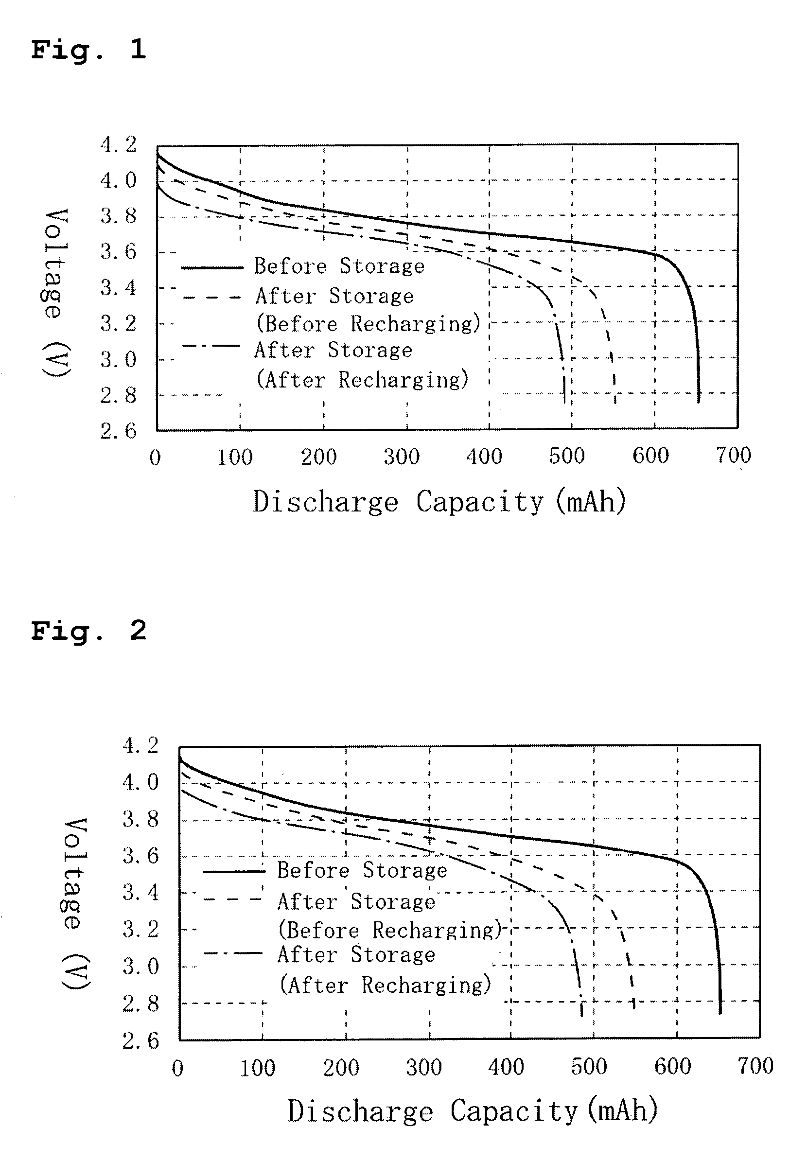
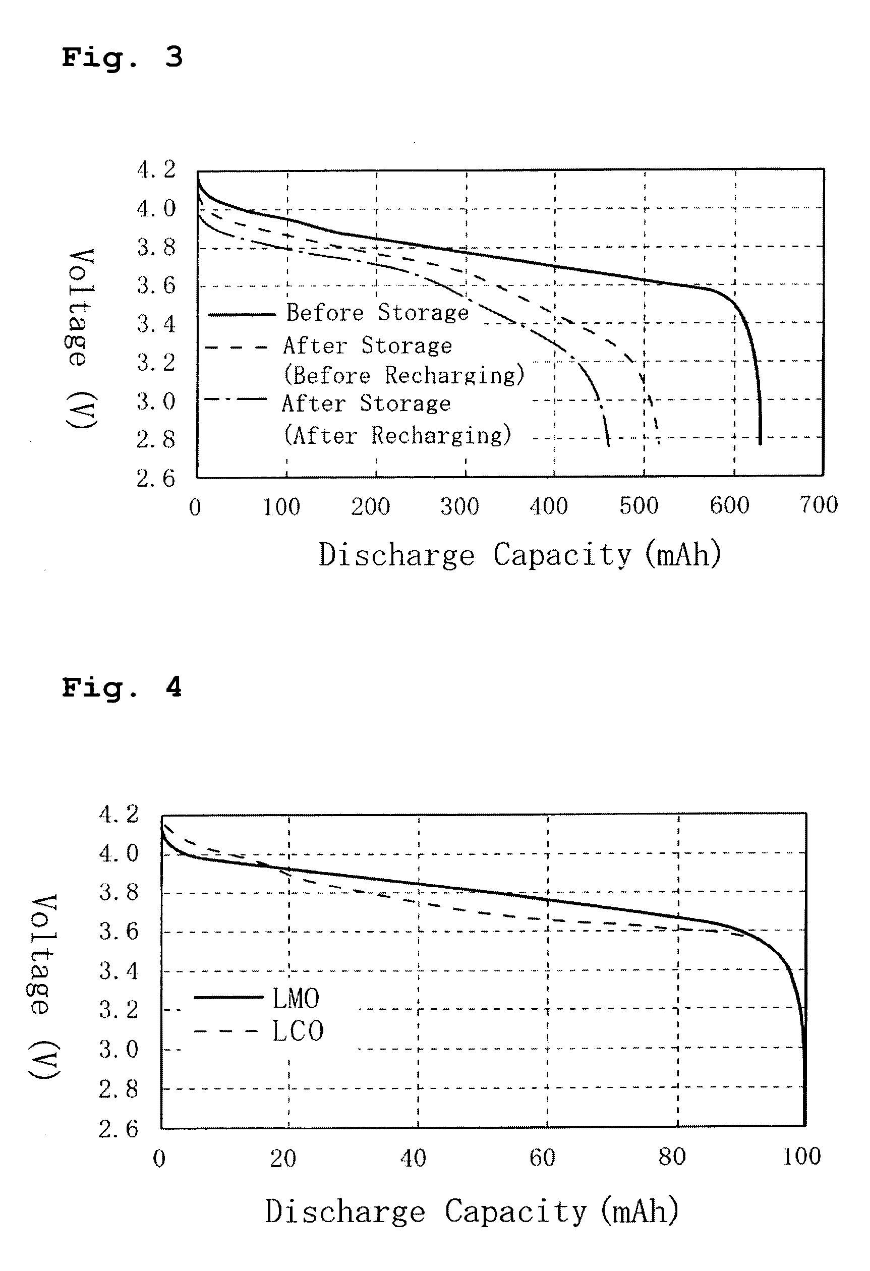
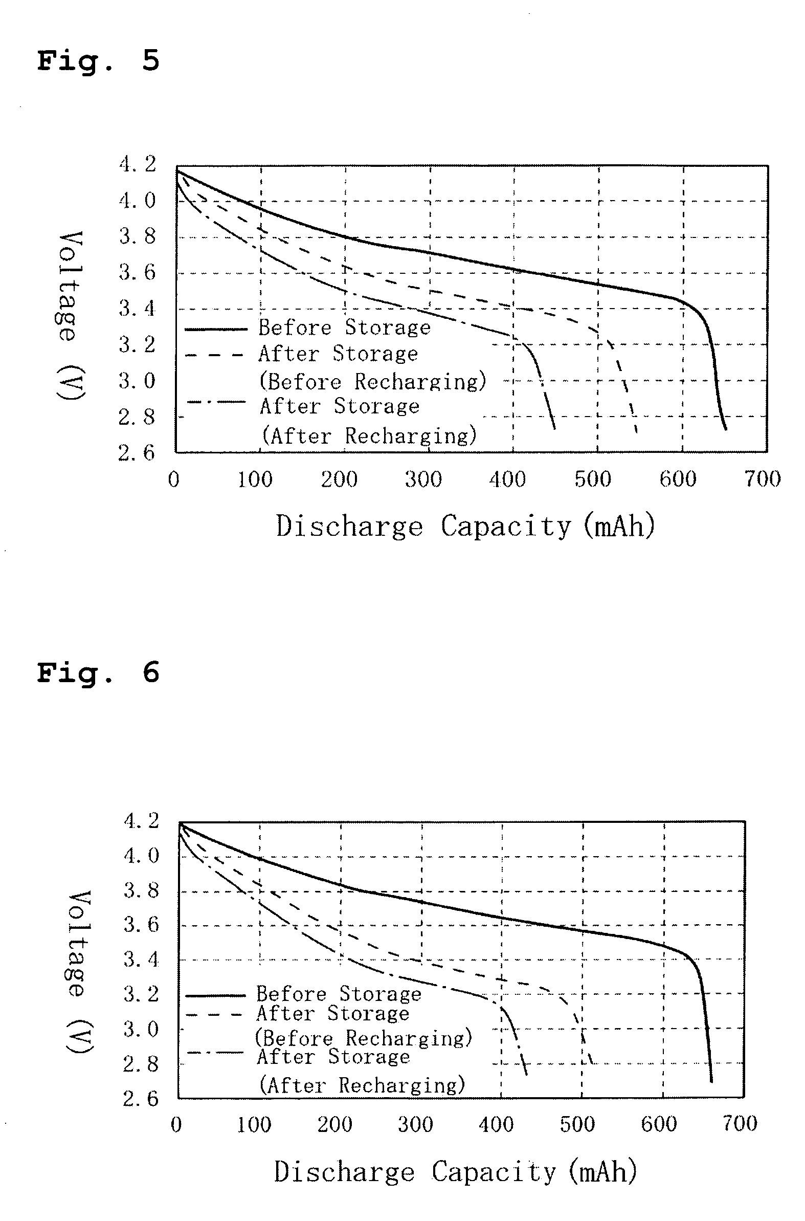
[0052] The battery characteristics of Battery A of the invention and Comparative Batteries X1 and X2 before and after high-temperature storage were studied. The results are set forth in Table 1, FIG. 1 (Battery A of the invention), FIG. 2 (Comparative Battery X1), and FIG. 3 (Comparative Battery X2). Specific conditions of the experiment were as follows.
[0053] First, the batteries were charged and discharged under the conditions set forth below to examine their discharge characteristics. Next, the batteries were stored under the conditions set forth below and thereafter their discharge characteristics were examined again. Lastly, the batteries were charged and discharged again under the conditions set forth below, and their discharge characteristics were studied. (See FIGS. 1 to 3.)
[0054] Charge-discharge Conditions
[0055] The batteries were charged at a constant current of 1C (650 mA) until the battery voltage reached 4.2 V and then charged at a constant voltage of 4.2 V until the current became 1/20 C (32.5 mA).
[0056] The batteries were discharged at a constant current of 1 C (650 mA) until the battery voltage reached 2.75 V.
[0057] A 10-minute resting period was provided between the charging and the discharging.
[0058] Storage Conditions
[0059] The batteries charged under the above charge conditions were stored for 4 days in an atmosphere at 80° C.
[0060] Also, the decreases in initial voltage after the storage with respect to battery voltage before the storage, the internal resistance increases, and the capacity retention ratios and the capacity recovery ratios that are defined by the following equations (1) and (2) were investigated with the batteries. (See Table 1.)
[0061] Capacity retention ratio=Discharge capacity after storage/Discharge capacity before storage×100 (%).
[0062] Capacity recovery ratio=Discharge capacity after storage and subsequent recharge/Discharge capacity before storage×100 (%) TABLE 1 Voltage decrease at initial Internal Capacity Capacity stage of resistance retention recovery discharge increase ratio ratio Battery (V) (mΩ) (%) (%) Battery A 0.12 17.2 75.6 84.6 Comparative 0.12 11.9 74.8 84.3 Battery X1 Comparative 0.12 16.6 73.4 82.0 Battery X2
[0063]FIG. 1 clearly demonstrates that Battery A of the invention exhibited a small voltage drop at the final stage of discharge (after the discharge capacity exceeded about 300 mAh) both before and after the recharging of the battery subsequent to the high-temperature storage. In contrast, as clearly seen from FIGS. 2 and 3, Comparative Batteries X1 and X2 showed large voltage drops at the final stage of discharge both before and after the recharging of the battery subsequent to the high-temperature storage. In particular, Comparative Battery X2 showed a very large voltage drop at the final stage of discharge. This is believed to be due to the following reasons.
[0064] Specifically, when a battery is stored at a high temperature, a positive electrode active material that produces a higher working voltage at the end of charge is more prone to damage. If this is the case, it is inferred that LCO is damaged primarily while LMO undergoes almost no damage in both Battery A of the invention and Comparative Batteries X1 and X2. The reason is that, as clearly seen from FIG. 4 the comparison between the charge-discharge curves of LCO and LMO indicates that LCO shows a higher working voltage at the end of charge than LMO. On the other hand, the present inventors have found that the positive electrode active material nearer the positive electrode current collector tends to affect the contour of battery discharge curve more than the positive electrode active material on the surface side of the positive electrode.
[0065] In Battery A of the invention, LMO, which is a positive electrode active material less prone to damage, is arranged near the positive electrode current collector while LCO, which is a positive electrode active material more prone to damage, is arranged on the surface side of the positive electrode; therefore, in Battery A of the invention, LMO affects the contour of the battery discharge curve to a greater extent, resulting in a small voltage drop at the final stage of discharge. By contrast, in Comparative Battery X1, LMO, which is less prone to damage, and LCO, which is more prone to damage, are arranged both near the positive electrode current collector and on the surface side of the positive electrode. Therefore, in Comparative Battery X1, both LCO and LMO affect the contour of the battery discharge curve, resulting in a greater voltage drop at the final stage of discharge. Furthermore, in Comparative Battery X2, LCO, which is the positive electrode active material more prone to damage, is arranged near the positive electrode current collector while LMO, which is the positive electrode active material less prone to damage, is arranged on the surface side of the positive electrode. Therefore, in Comparative Battery X2, LCO affects the contour of battery discharge curve to a greater extent, resulting in an even greater voltage drop at the final stage of discharge.
[0066] Table 1 also shows that there was no difference in voltage decrease at the initial stage of discharge between Battery A of the invention and Comparative Battery X1, and also that there was little difference in their capacity retention ratios and their capacity recovery ratios. It is believed that the reason is that Battery A of the invention showed an increase in the battery internal resistance, as clearly seen from Table 1, although its voltage drop at the final stage of discharge was small, while Comparative Battery X1 did not show a considerable increase in the battery internal resistance, although its voltage drop at the final stage of discharge was great. It is believed that the reason why the internal resistance in Battery A of the invention increased is that the amount of binder agent at the interface between the first positive electrode active material layer and the second positive electrode active material layer was greater than that in the rest of the regions. In Comparative Battery X2, the capacity retention ratio and the capacity recovery ratio were lower than those of Battery A of the invention and Comparative Battery X1. This is because, in Comparative Battery X2, the voltage drop at the final stage of discharge was great and moreover, as clearly seen from Table 1, the battery internal resistance increased.

Example

EXAMPLE B
[0067] A battery was fabricated in the same manner as in Example A in the first embodiment, except that in place of LMO, lithium nickel oxide (LiNi0.8Co0.2O2, hereinafter also abbreviated as LNO) was used as the positive electrode active material in the first positive electrode active material layer and that the mass ratio of the positive electrode active materials in the positive electrode was LCO:LNO=70:30.
[0068] The battery thus fabricated is hereinafter referred to as Battery B of the invention.
COMPARATIVE EXAMPLE Y
[0069] A battery was fabricated in the same manner as in Comparative Example X1 in the first embodiment, except that in place of LMO, LNO was used as the positive electrode active material in the positive electrode active material-layer and that the mass ratio of the positive electrode active materials in the positive electrode was LCO:LNO=70:30.
[0070] The battery thus fabricated is hereinafter referred to as Comparative Battery Y.
[0071] Experiment
[0072] The battery characteristics of Battery B of the invention and Comparative Battery Y before and after high-temperature storage were studied. The results are set forth in Table 2, FIG. 5 (Battery B of the invention), and FIG. 6 (Comparative Battery Y). Specific conditions of the experiment were the same as those of the experiment in first embodiment. TABLE 2 Voltage decrease at initial Internal Capacity Capacity stage of resistance retention recovery discharge increase ratio ratio Battery (V) (mΩ) (%) (%) Battery B 0.10 18.4 69.6 84.2 Comparative 0.10 15.6 65.5 77.9 Battery Y
[0073] As clearly seen from FIG. 5, Battery B of the invention exhibited a small voltage drop at the final stage of discharge (after the discharge capacity exceeded about 300 mAh) both before and after the recharging of the battery subsequent to the high-temperature storage. In contrast, as clearly seen from FIG. 6, Comparative Battery Y showed a large voltage drop both before and after the recharging of the battery subsequent to the high-temperature storage. It is believed that the results are due to the same reasons as discussed in the experiment in the first embodiment.
[0074] Table 2 also clearly demonstrates that although there was no difference in voltage drop at the initial stage of discharge between Battery B of the invention and Comparative Battery Y, Battery B of the invention exhibited improved capacity retention ratio and capacity recovery ratio over those of Comparative Battery Y. The reason is believed to be as follows. With Battery B of the invention, the voltage drop at the final stage of discharge was small, and moreover, as clearly seen from Table 2, an increase in the battery internal resistance was prevented. In contrast, with Comparative Battery Y, the voltage drop at the final stage of discharge was great, and moreover, as clearly seen from Table 2, the increase in battery internal resistance was similar to that of Battery B of the invention.
[0075] Other Variations
[0076] (1) The positive electrode active material is not limited to lithium cobalt oxide, spinel-type lithium manganese oxide, and lithium nickel oxide. Other materials may be used such as an olivine-type lithium phosphate and a layered lithium-nickel compound. The working voltage at the end of charge for these positive electrode active materials is as shown in Table 3. Herein, it is necessary that a positive electrode active material that shows a low working voltage at the end of charge be selected for the first positive electrode active material layer (the layer nearer the positive electrode current collector). TABLE 3 Type of positive electrode Working voltage at active material end of charge* Lithium cobalt oxide Highest (LiCoO2) Spinel-type lithium manganese Low oxide (LiMn2O4) Lithium nickel oxide Fairly high (LiNiO2) Olivine-type lithium iron Very low phosphate (LiFePO4) Layered lithium-nickel Fairly high compound (LiNi1/3Mn1/3Co1/3O2)
*Working voltages at the end of charge shown are relative to that of lithium cobalt oxide.
[0077] (2) In the foregoing examples, a spinel-type lithium manganese oxide or lithium nickel oxide is used alone as the active material of the first positive electrode active material layer, but such a configuration is merely illustrative of the invention. For example, it is of course possible to use a mixture of spinel-type lithium manganese oxide and lithium nickel oxide for the active material of the first positive electrode active material layer. Likewise, it is also possible to use a mixture for the second positive electrode active material layer.
[0078] (3) The structure of the positive electrode is not limited to the two-layer structure, and a structure comprising three or more layers may of course be employed.
[0079] (4) The method for mixing the positive electrode mixture is not limited to the above-noted mechanofusion method. Other possible methods include a method in which a mixture is dry-blended while milling the mixture with a Raikai-mortar, and a method in which the mixture is wet-mixed and dispersed directly in a slurry.
[0080] (5) The negative electrode active material is not limited to graphite, and various other materials may be employed, such as coke, tin oxides, metallic lithium, silicon, and mixtures thereof, as long as the materials are capable of intercalating and deintercalating lithium ions.
[0081] (6) The lithium salt in the electrolyte solution is not limited to the LiPF6, and various other substances may be used, including LiBF4, LiN(SO2CF3)2, LiN(SO2C2F5)2, LiPF6−X(CnF2n+1)X (wherein 1
[0082] (7) The present invention may be applied to gelled polymer batteries as well as liquid-type batteries. In this case, examples of the polymer material include polyether-based solid polymer, polycarbonate solid polymer, polyacrylonitrile-based solid polymer, oxetane-based polymer, epoxy-based polymer, and copolymers or cross-linked polymers comprising two or more of these polymers, as well as PVDF. A gelled solid electrolyte in which any of these polymer materials, a lithium salt, and an electrolyte are combined may be used.
[0083] The present invention is also applicable to large-sized batteries for, for example, in-vehicle power sources for electric automobiles or hybrid automobiles, as well as the device power sources for mobile information terminals such as mobile telephones, notebook computers, and PDAs.
[0084] Only selected embodiments have been chosen to illustrate the present invention. To those skilled in the art, however, it will be apparent from the foregoing disclosure that various changes and modifications can be made herein without departing from the scope of the invention as defined in the appended claims. Furthermore, the foregoing description of the embodiments according to the present invention is provided for illustration only, and not for limiting the invention as defined by the appended claims and their equivalents.
[0085] This application claims priority based on Japanese patent application No. 2004-213112, filed Jul. 21, 2004, which is incorporated herein by reference.

PUM

no PUM

Description & Claims & Application Information

We can also present the details of the Description, Claims and Application information to help users get a comprehensive understanding of the technical details of the patent, such as background art, summary of invention, brief description of drawings, description of embodiments, and other original content. On the other hand, users can also determine the specific scope of protection of the technology through the list of claims; as well as understand the changes in the life cycle of the technology with the presentation of the patent timeline. Login to view more.

Similar technology patents

Dual-microphone noise reduction and echo elimination circuit

ActiveCN107734429ALow working voltageOverall Current Consumption ReductionTwo-way loud-speaking telephone systemsMicrophones signal combinationPhysicsMicrophone
Owner:SHENZHEN COOPERATION TECH

Classification and recommendation of technical efficacy words

Why Eureka
Try Eureka