High Vacuum Plasma-Assisted Chemical Vapor Deposition System

a technology plasma, which is applied in the direction of chemical vapor deposition coating, plasma technique, coating, etc., can solve the problems of r-pecvd not offering any further temperature reduction, the silicon oxide itself will not be able to meet these performance requirements, and the inclusion of unwanted impurities,

Inactive Publication Date: 2006-02-02
COLORADO SCHOOL OF MINES
View PDF0 Cites 315 Cited by
  • Summary
  • Abstract
  • Description
  • Claims
  • Application Information

AI Technical Summary

Benefits of technology

[0007] The present invention is directed to an apparatus for implementing high vacuum, plasma assisted, chemical vapor deposition for the synthesis of a thin film on a substrate. In one embodiment, the apparatus is comprised of a reactor vessel that defines a substantial portion of a chamber suitable for the establishment of a thin film on a substrate; a support surface located within the vessel for supporting a substrate; a structure for providing a reactive species to the chamber; and a port in the vessel for conveying a volatile metal vapor into the chamber. In addition, the apparatus comprises a pump that is capable of producing a substantially collisionless environment in the chamber for gaseous substances. Potential characteristics of a collisionless environment are a pressure below about 1 mTorr or a Knudsen number greater than about 10. A collisionless environment substantially eliminates gas-phase chemistry. As a consequence, surface chemistry substantially determines the interaction between the reactive species and the volatile metal vapor. In one embodiment, the pump is capable of producing a pressure within the chamber of less than 100 μTorr.

Problems solved by technology

Silicon oxide itself will be unable to satisfy these performance requirements, due to the significant amount of direct tunneling that occurs at this thickness.
Direct contact with the plasma exposes the growing film to ion bombardment, which can lead to defect formation and the inclusion of unwanted impurities.
R-PECVD does not offer any further temperature reduction relative to PECVD.

Method used


Image

  • High Vacuum Plasma-Assisted Chemical Vapor Deposition System
  • High Vacuum Plasma-Assisted Chemical Vapor Deposition System
  • High Vacuum Plasma-Assisted Chemical Vapor Deposition System

Examples


Embodiment Construction

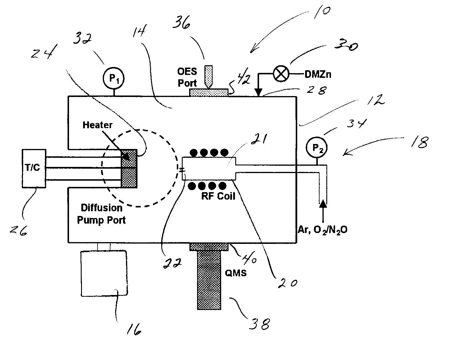
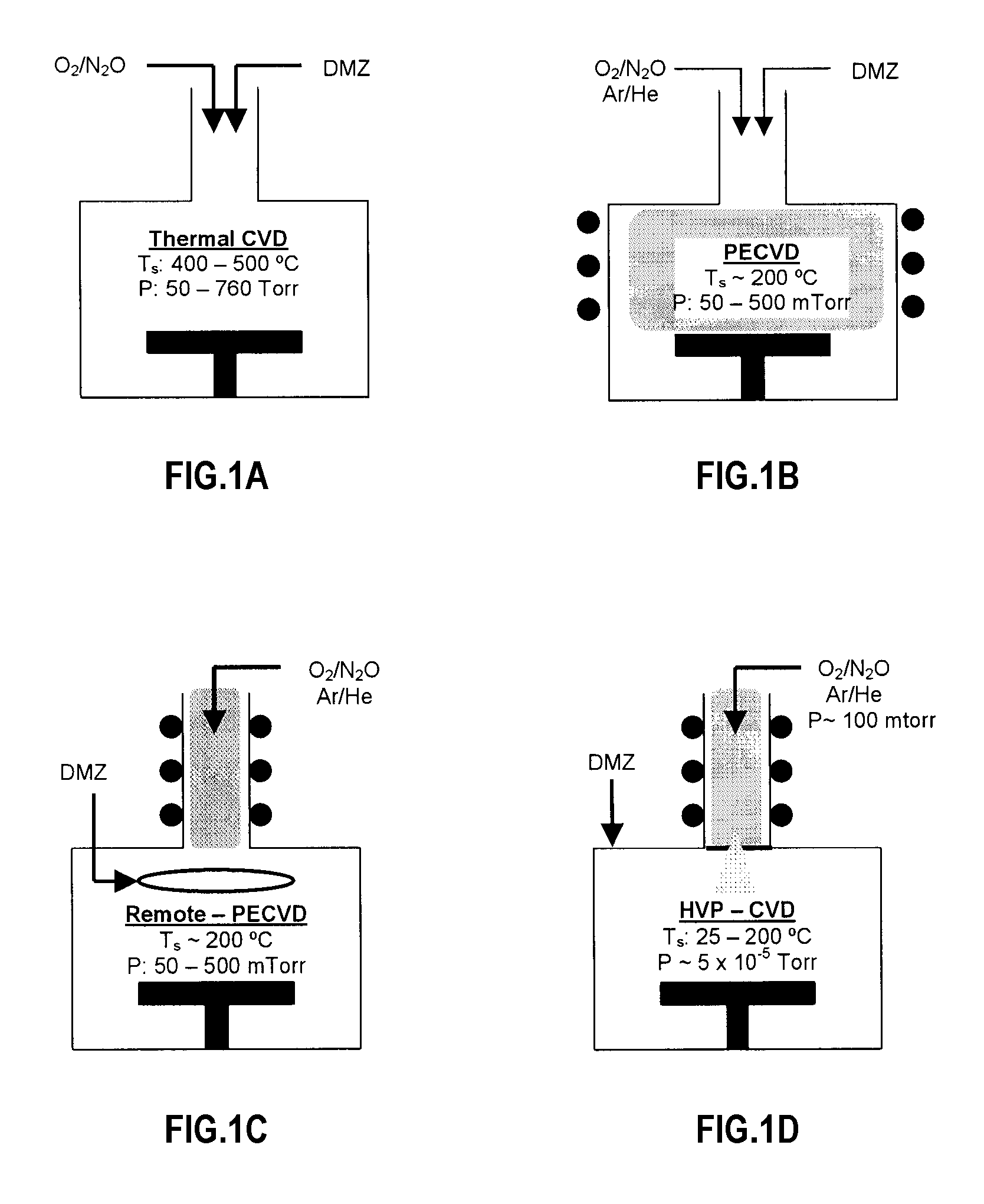
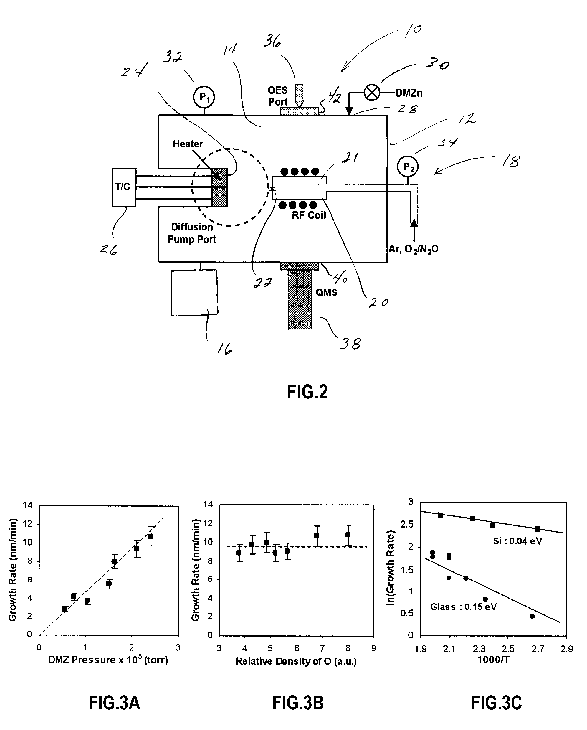
[0019]FIG. 1D is a schematic of a high vacuum, plasma-assisted, chemical vapor deposition (HVP-CVD) system. Like remote PECVD, the plasma is removed from the substrate in HVP-CVD, eliminating or substantially eliminating ion bombardment. Unlike remote PECVD, the reactive species effuse from the plasma into a high vacuum deposition chamber under substantially collisonless conditions. A high vacuum for purposes of HVP-CVD is below about 1 mTorr. In the illustrated embodiment, the high vacuum is approximately 5×10⁻⁵ Torr. The organometallic precursor is also introduced into the high vacuum chamber. All other CVD techniques operate under continuum flow conditions where extensive gas-phase collisions and gas-phase chemistry occur. The most important distinction of HVP-CVD is that gas-phase chemistry is eliminated or substantially eliminated, and precursor decomposition occurs exclusively or substantially through surface-mediated routes. It is in many ways similar to plasma-assisted molec...


PUM

PropertyMeasurementUnit
pressureaaaaaaaaaa
pressureaaaaaaaaaa
pressureaaaaaaaaaa

Abstract

The invention is directed to a novel approach to thin film synthesis that is described as high vacuum plasma-assisted chemical vapor deposition (HVP-CVD). In one application of HVP-CVD, atomic oxygen and organometallic precursors are simultaneously introduced into a high vacuum chamber. Gas-phase chemistry is eliminated or substantially eliminated in the collisionless or substantially collisionless environment, allowing the surface chemistry between atomic oxygen and the precursor(s) to be interrogated directly. In preliminary work it has been observed that the presence of atomic oxygen greatly accelerates the desorption of organic ligands, facilitating oxide formation. The prominent advantages of the HVP-CVD include reduced substrate temperature, significant rates, inherent uniformity, facilitated doping, and the ability to directly study these processes in-situ with high vacuum diagnostics that are not compatible with conventional CVD technologies.

Description

BACKGROUND [0001] Thin film metal oxides are critical components in numerous technological devices, including integrated circuits (IC), solar cells, light emitting diodes, UV lasers, electrochromic windows, phosphor displays, and fuel cells. The National Technology Roadmap for Semiconductors projects that next generation devices will require gate dielectrics with a thickness equivalent (tox, eq)<1 nm of silicon oxide. Silicon oxide itself will be unable to satisfy these performance requirements, due to the significant amount of direct tunneling that occurs at this thickness. In response to this problem, alternative oxides with dielectric constants (κ) much greater than SiO2 (κ˜3.8) are being pursued. These high κ materials can achieve the desired tox, eq while maintaining sufficient thickness to minimize leakage current. [0002] The leading candidates for this application include transition metal oxides such as TiO2, ZrO2, HfO2, Y2O3, and Ta2O5, as well as their alloys with SiO2 (...

Claims


Application Information

Patent Timeline
Patent Type & Authority Applications(United States)
IPC IPC(8): C23C16/00H05H1/24
CPCC23C16/407H01J2237/2001H01J37/32972C23C16/452
Inventor WOLDEN, COLIN A.
Owner COLORADO SCHOOL OF MINES
Why Eureka
Try Eureka