Thermoelectric conversion device, and cooling method and power generating method using the device

Active Publication Date: 2006-02-02
PANASONIC CORP
View PDF3 Cites 24 Cited by
  • Summary
  • Abstract
  • Description
  • Claims
  • Application Information

AI Technical Summary

Benefits of technology

[0018] According to the present invention, higher thermoelectric conversion performance can be obtained in a wide temperature region than was conventionally possible by utilizing the thermoelectric conversion charac

Problems solved by technology

With a layered substance, the thermoelectric conversion performance of the electrically conducting layer regarding its in-p

Method used


Image

  • Thermoelectric conversion device, and cooling method and power generating method using the device
  • Thermoelectric conversion device, and cooling method and power generating method using the device
  • Thermoelectric conversion device, and cooling method and power generating method using the device

Examples


embodiment 1

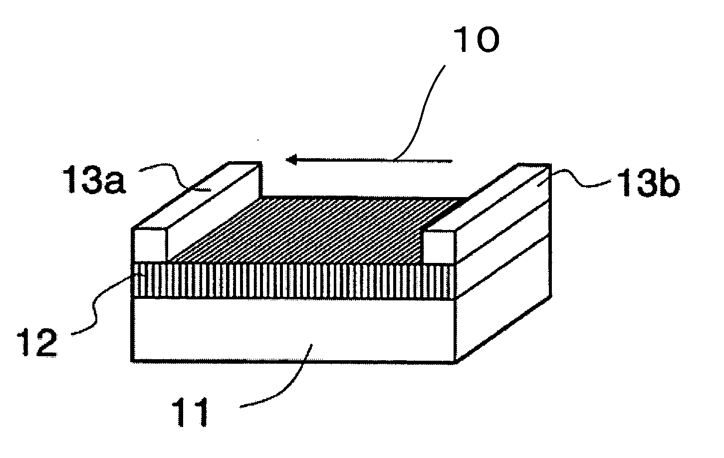
[0041] A thermoelectric conversion device shown in FIG. 1 is furnished with a plate-shaped substrate 11, a thermoelectric-conversion film 12 on the substrate 11, and a pair of electrodes 13a, 13b arranged to the right and left of the substrate 11 so as to be in contact with the thermoelectric-conversion film 12.

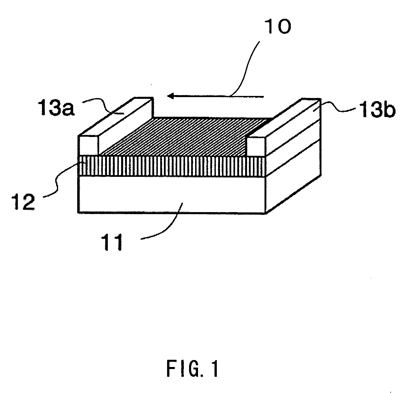
[0042]FIG. 2 illustrates a crystal structure of the thermoelectric-conversion film 12. The thermoelectric-conversion film 12 has a layered structure in which electrically conducting layers 22 and electrically insulating layers 23 are alternately arranged. In other words, the thermoelectric-conversion film 12 is made of a crystalline thin film in which the electrically conducting layers 22 and the electrically insulating layers 23 are alternately arranged.

[0043] In terms of crystallography, the interlayer direction, i.e., the direction perpendicular to the layer surfaces, is referred to as a c-axis direction 10. The pair of electrodes 13a and 13b are arranged so that current...

example 1

[0086] A film of layered oxide Na0.4CoO2 was deposited on a 10 mm-square and 100-μm-thick A plane substrate of sapphire Al2O3. The deposition was carried out by RF magnetron sputtering using a 4-inch-diameter Na0.5CoO2 sintered compact target.

[0087] Pre-sputtering was carried out at an output power of 60 W for 1 hour in an atmosphere gas containing 80% Ar and 20% O2 that was kept at 5.0 Pa. Thereafter, deposition was performed on the substrate heated to 700° C. over a duration of 5 hours under the same conditions as in the pre-sputtering. Subsequently, the heated thin film on the substrate was cooled for 2 hours to room temperature in an oxygen atmosphere. Consequently, a thin film having metallic luster and a film thickness of 1000 nm was obtained.

[0088] Energy dispersive X-ray fluorescence analysis confirmed that the composition ratio of Na and Co in the thin film was approximately Na:Co=0.4:1.

[0089] The result of the X-ray diffraction analysis for the Na0.4CoO2 thin film thus ...

example 2

[0103] Using a 4-inch target material composed of a sintered compact made of powders of CaO2 and Co3O4, a thin film having a film thickness of 1000 nm was grown on a sapphire M-plane substrate of 10 mm square and 100 μm thick under the same sputtering conditions as in Example 1.

[0104] Energy dispersive X-ray fluorescence analysis confirmed that the composition ratio of Ca and Co in this thin film was approximately Ca:Co=0.5:1. The result of X-ray diffraction analysis for this Ca0.5CoO2 thin film is shown in FIG. 9. Besides the diffraction peak originating from the sapphire substrate, only the peak indexed as (020) due to the diffraction from the thin film was observed.

[0105] This demonstrated that the Ca0.5CoO2 thin film was epitaxially grown so that its (010) plane became parallel to the substrate. In addition, four-axis x-ray diffraction analysis confirmed that the c axis of the crystal of Ca0.5CoO2 oriented in the plane of the thin film.

[0106] The Ca0.5CoO2 thin film had shown...


PUM


Abstract

The present invention provides a thermoelectric conversion device having high thermoelectric conversion performance. In this device, electrodes are arranged so that electric current flows in an interlayer direction of a layered substance, unlike the arrangements derived from common knowledge in the art. In the thermoelectric conversion device according to the present invention, a thermoelectric-conversion film is obtained through epitaxial growth and formed by arranging an electrically conducting layer and an electrically insulating layer alternately; the electrically conducting layer has an octahedral crystal structure in which a transition metal atom M is positioned at its center and oxygen atoms are positioned at its vertexes; and the electrically insulating layer includes a metal element or a crystalline metal oxide. The c axis of the layered substance made of the electrically conducting layer and the electrically insulating layer is parallel to an in-plane direction of the substrate, and a pair of electrodes are arranged so that electric current flows along the c axis.

Description

BACKGROUND OF THE INVENTION [0001] 1. Field of the Invention [0002] The present invention relates to a thermoelectric conversion device for conducting conversion between thermal energy and electric energy by the Peltier effect or the Seebeck effect. [0003] 2. Description of the Related Art [0004] Thermoelectric power generation is a technology for directly converting thermal energy into electric energy with the use of the Seebeck effect, a phenomenon in which a temperature difference given to opposing ends of a substance causes a thermal electromotive force in proportion to the temperature difference, whereby electric power can be taken out by connecting a load externally and forming a closed circuit. This technology has been in practical use as power supplies for remote areas, power supplies for aerospace use, power supplies for military use, and so forth. [0005] Thermoelectric cooling is a technology that utilizes the Peltier effect, a phenomenon in which heat is transferred by el...

Claims


Application Information

Patent Timeline
IPC IPC(8): H01L35/12H01L35/28H01L35/22H01L35/34
CPCH01L35/34H01L35/22H10N10/855H10N10/01
Inventor YOTSUHASHI, SATOSHIKANNO, TSUTOMUADACHI, HIDEAKIODAGAWA, AKIHIROSUGITA, YASUNARI
Owner PANASONIC CORP
Why Eureka
Try Eureka