Beam control system with extended beacon and method

a beam control and beam technology, applied in the field of optics, can solve the problems of large near-field aero-optic distortion, error in optical path-length difference (opd), and difficulty in implementing two beam systems of the prior art, and achieve the effect of improving the accuracy of beam control and reducing the cost of implementation

Active Publication Date: 2006-02-02
RAYTHEON CO
View PDF3 Cites 65 Cited by
  • Summary
  • Abstract
  • Description
  • Claims
  • Application Information

AI Technical Summary

Benefits of technology

[0009] The need in the art is addressed by the beam control system and method of the present invention. Generally, the inventive beam control system and method includes an arrangement for receiving a first beam of electromagnetic energy; tracking the target using an active fine track sensor and fast steering mirror, measuring wavefront aberrations in the illuminator beam with an active wavefront sensor; and removing the global wavefront tilt modes (angular jitter) from the measured wavefront aberrations to provide only the higher order wavefront error modes which are used in an adaptive optics control system to predistort the high power beam in order to correct the high order errors.
[0010] In the illustrative embodiment, the invention uses a traditional (quad-cell) Shack-Hartmann wavefront sensor to measure the wavefront aberrations due to the aero-optic aberrations in the near flowfield around the turret and aircraft and atmospheric turbulence;. The adaptive optics processor electronically removes the tilt (angular jitter) from this measurement, which is corrupted by the illuminator beam motion at the target, leaving only the higher-order components, which include focus, astigmatism, coma, trefoil, and others of even greater Zerni

Problems solved by technology

Although the flowfield introduces severe time-varying wavefront errors, these optical path-length difference (OPD) errors occur only within the first tens of meters of propagation and the isoplanatic angle for such a thin, near-field aero-optic distortion is typically large, encompassing the en

Method used


Image

  • Beam control system with extended beacon and method
  • Beam control system with extended beacon and method
  • Beam control system with extended beacon and method

Examples


Embodiment Construction

[0018] Illustrative embodiments and exemplary applications will now be described with reference to the accompanying drawings to disclose the advantageous teachings of the present invention.

[0019] While the present invention is described herein with reference to illustrative embodiments for particular applications, it should be understood that the invention is not limited thereto. Those having ordinary skill in the art and access to the teachings provided herein will recognize additional modifications, applications, and embodiments within the scope thereof and additional fields in which the present invention would be of significant utility.

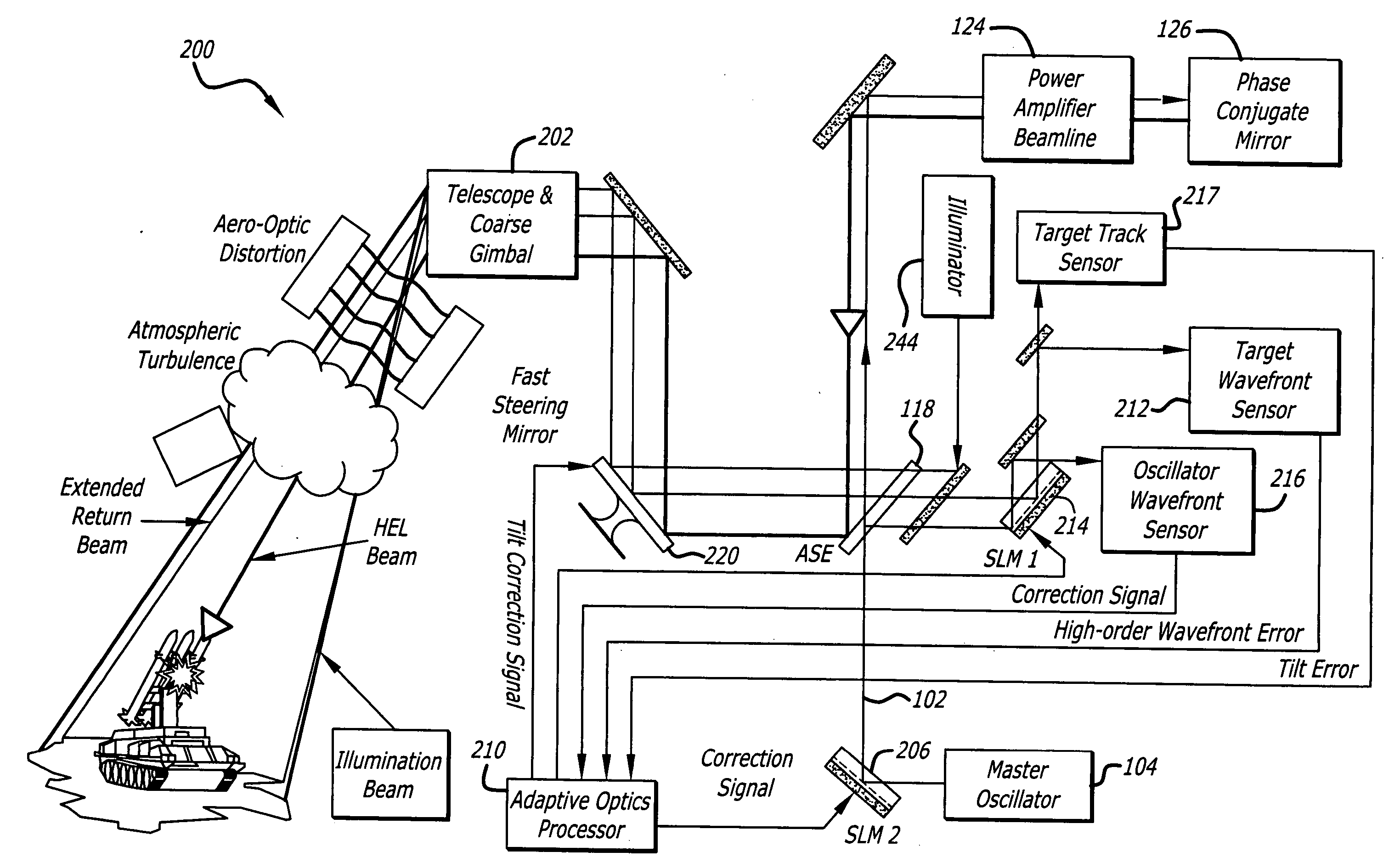
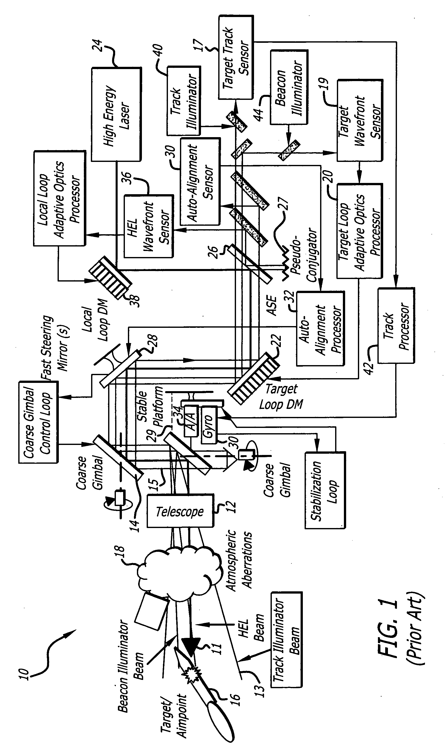
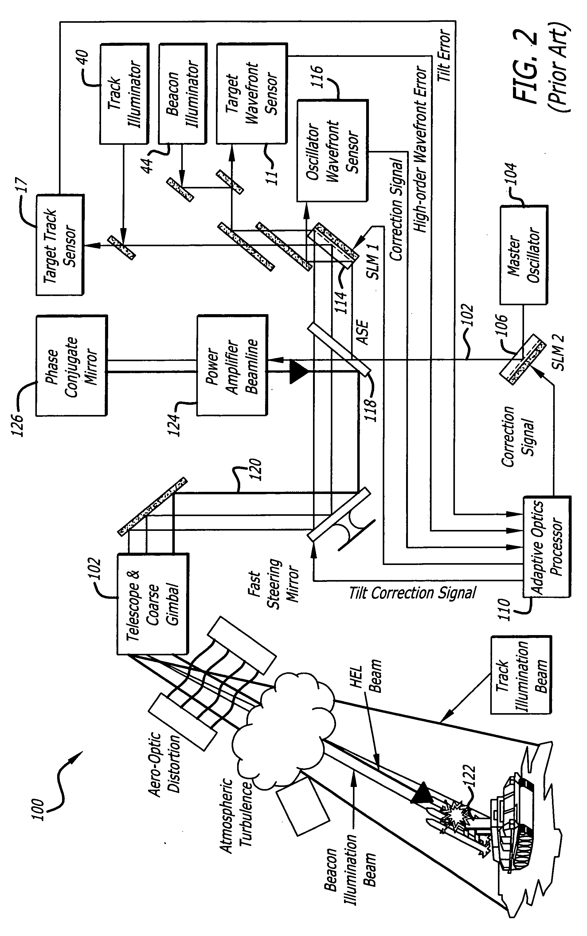
[0020] As discussed above, advanced laser beam control systems typically use a two-illuminator system. The first is a track illuminator laser which floods the target area with laser light allowing an active fine track sensor to track the hard body of a target. The second is a beacon illuminator laser which provides a narrow beam on the target aim...


PUM


Abstract

A beam control system and method: The inventive system includes, an arrangement for receiving a first beam of electromagnetic energy; measuring wavefront aberrations in the first beam with a wavefront sensor; and removing global tilt from the measured wavefront aberrations to provide higher order aberrations for beam control. In the illustrative embodiment, the invention uses a traditional (quad-cell) Shack-Hartmann wavefront sensor to measure wavefront aberrations. An adaptive optics processor electronically removes the global tilt (angular jitter) from this measurement leaving only the higher-order Zernike components. These higher-order aberrations are then applied to wavefront control elements, such as deformable mirrors or spatial light modulators that correct the tracker image and apply a conjugate distortion to the wavefront of the outgoing HEL beam. A track error (angular jitter) component is supplied by a separate fine track sensor. This jitter error is then applied by the adaptive optics processor to a fast steering mirror, which corrects jitter in the tracker image and applies a compensating distortion to the LOS of the HEL beam.

Description

BACKGROUND OF THE INVENTION [0001] 1. Field of the Invention [0002] The present invention relates to optics. More specifically, the present invention relates to systems and methods for directing and correcting high-power beams of electromagnetic energy. [0003] 2. Description of the Related Art [0004] Directed energy weapons and specifically high-energy laser (HEL) weapons are being considered for variety of military applications with respect to a variety of platforms, e.g., spaceborne, airborne and land based systems to name a few. These weapons generally involve the use of the laser or other source of a high-power electromagnetic radiation beam to track and destroy a target. To achieve mission objectives, directed energy weapons must be accurately steered and optimally focused. Steering involves line-of-sight control while focusing, with respect to HEL weapons, involves wavefront error correction. [0005] In particular, high energy laser (HEL) beam control systems used on high perfo...

Claims


Application Information

Patent Timeline
IPC IPC(8): G01J1/20
CPCG01J1/0266G02B26/06G01J9/00F41H13/005
Inventor BYREN, ROBERT W.
Owner RAYTHEON CO
Why Eureka
Try Eureka