Miniature wideband bias tee

a bias tee and wideband technology, applied in the field of bias tees, can solve the problems of low parasitic resistance, poor high frequency electrical performance of bias tees, large parasitic capacitance, etc., and achieve the effect of low cost and small package siz

Active Publication Date: 2006-02-02
SCI COMPONENTS
View PDF4 Cites 13 Cited by
  • Summary
  • Abstract
  • Description
  • Claims
  • Application Information

AI Technical Summary

Benefits of technology

[0010] It is a feature of the invention to provide a miniature wideband b...

Problems solved by technology

Unfortunately, when the inductance is large, the parasitic capacitance is also large and the parasitic resistance low.
The result is that the electrical performance of the bias tee is poor at high frequencies.
Unfortunately, the multiple ferrite cores take up excessive space when mounted...

Method used


Image

  • Miniature wideband bias tee
  • Miniature wideband bias tee
  • Miniature wideband bias tee

Examples


Embodiment Construction

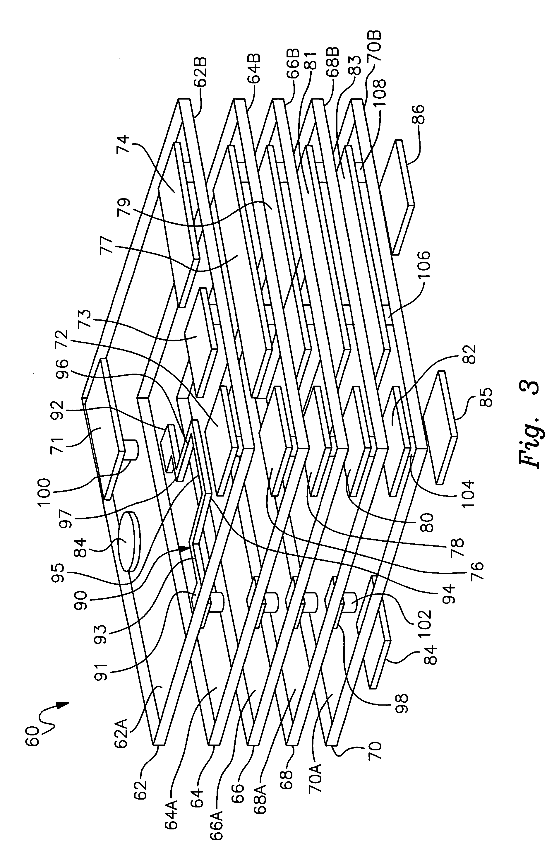
[0021] Referring to FIG. 3, an exploded view of a low temperature co-fired ceramic (LTCC) substrate 60 is shown. Substrate 60 has a top surface 62A and a bottom surface 70B. LTCC substrate 60 is comprised of multiple layers of low temperature co-fired ceramic material. Planar layers 62, 64, 66, 68 and 70 are all stacked on top of each other and form a unitary structure 60 after firing in an oven. LTCC layers 62-70 are commercially available in the form of a green unfired tape from Dupont Corporation. Each of the layers has a top surface, 62A, 64A, 66A, 68A and 70A. Similarly, each of the layers has a bottom surface, 62B, 64B, 66B, 68B and 70B.

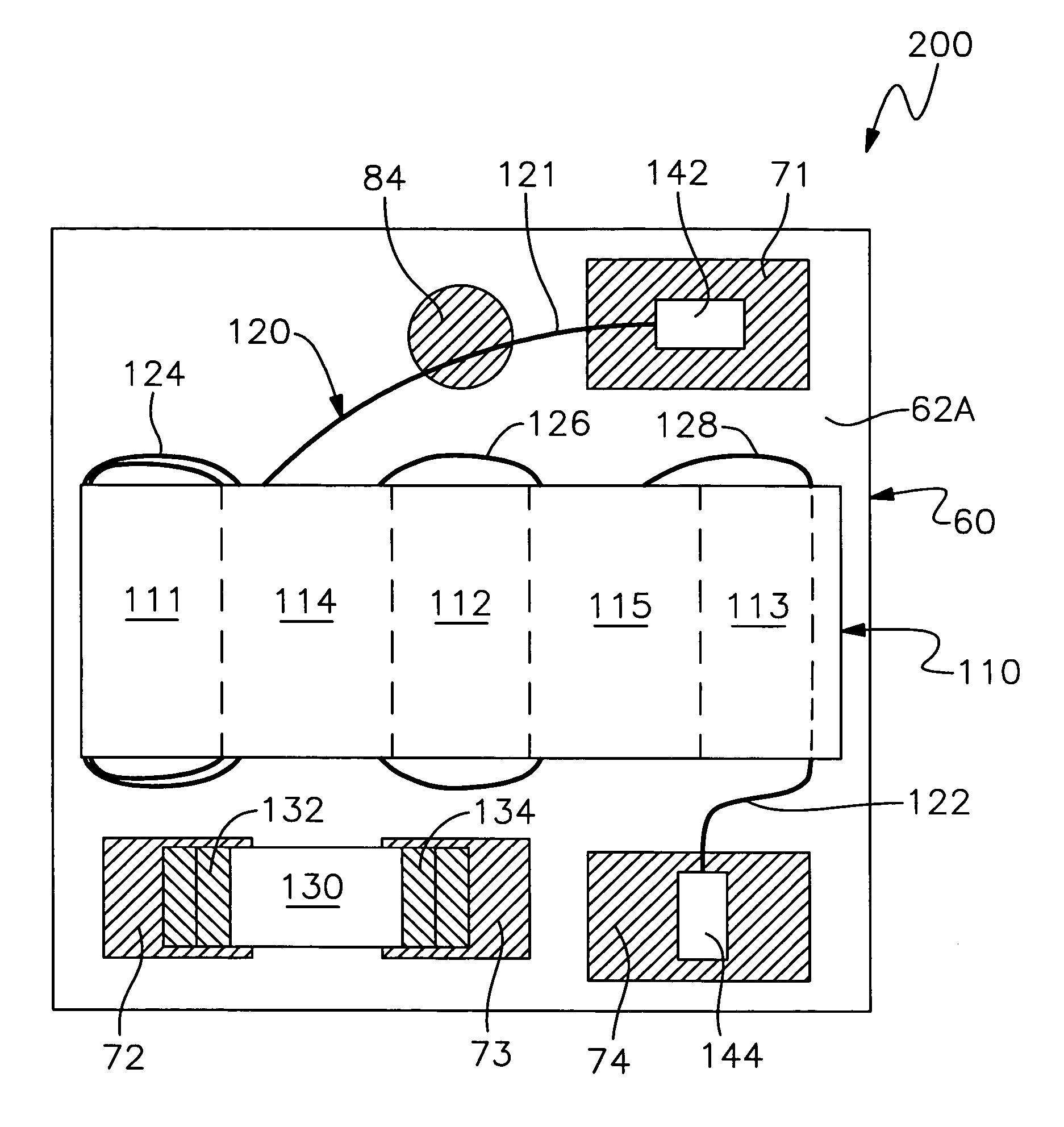
[0022] The layers have several circuit features that are patterned on the surfaces. Layer 62 has several circuit features that are patterned on surface 62A. Surface 62A has four terminals 71, 72, 73 and 74 and an orientation mark 84. The terminals are electrically connected to vias. Terminal 71 is connected to via 100. Terminal 72 is connected...


PUM


Abstract

A miniature wideband bias tee that has a small package size. The bias tee has a low temperature co-fired ceramic substrate with a top surface and a bottom surface. A first inductor is located within the substrate. A second inductor is attached to the top surface and has a core with a wire wound on the core. Terminals are located on the top and bottom surfaces. Ends of the wire are connected to terminals on the top surface. A capacitor is mounted to terminals on the top surface. Several vias extend through the substrate and electrically connect the terminals to the inductor and capacitor.

Description

BACKGROUND [0001] 1. Field of the Invention [0002] This invention relates to bias tees used with radio frequency (RF) and microwave frequency signals in general and more particularly to a miniature wideband bias tee that has a small package size and that can be manufactured at low cost. [0003] 2. Description of the Related Art [0004] Bias tees are used in various devices. A bias tee is used with radio frequency and microwave frequency signals to couple a direct current (DC) voltage onto a line used for alternating current (AC or RF) signals. A bias tee can also separate a combined RF and DC signal into separate RF and DC signals. The bias tee can remove the DC component of a composite signal in order to isolate a RF component. [0005] Referring to FIG. 1, a schematic diagram of a bias tee 20 is shown. Bias tee 20 has three ports, DC, RF and RF+DC. A low frequency or DC signal is applied to port DC. A high frequency or RF signal is applied to port RF. A combined signal results at port...

Claims


Application Information

Patent Timeline
IPC IPC(8): H03H7/01
CPCH01F27/027H03H7/46H03H7/06H01F2017/067
Inventor JI, DAXIONG
Owner SCI COMPONENTS
Why Eureka
Try Eureka