Refresh period generating circuit

Active Publication Date: 2006-02-02
LONGITUDE LICENSING LTD
View PDF3 Cites 55 Cited by
  • Summary
  • Abstract
  • Description
  • Claims
  • Application Information

AI Technical Summary

Benefits of technology

[0028] As described above, according to the invention, the oscillation circuit that determines a refresh period of the DRAM cell is configured with an analog-system oscillation circuit with positive temperature dependence (such that the oscillating frequency increases at high temperatures), and using the fact that a point where the temperature dependence of oscillation disappears exists at high temperature and low temperatures, the oscillating frequency is varied in digital form from such a point where the temperature variation substantially dis

Problems solved by technology

In other words, in the case of considering 0.5 times/10° C. as the temperature dependence of the data retention time of the DRAM cell, the temperature range that can be covered is only from 20° C. to 30° C., and it is difficult to sufficiently reduce the current consumption at low temperatures.
Moreover, to further reduce AC operation part (dynamic current) of current consumption at low temperatures in half, it is required to further reduce a variation range of the oscillating frequency to lower frequencies particularly at low temperatures, but such reduction is difficult.
Thus, the conventional analog-system refresh period generating circuit 100 has problems in terms of power reduction of the DRAM product for use in the portable device.
In particular, since the idea of varying the refresh period originates from reduction in current consumption when the temperature is low, it is useless trading off an increase in current consumption for suppression of fluctuations.
Accordingly, when effects are

Method used


Image

  • Refresh period generating circuit
  • Refresh period generating circuit
  • Refresh period generating circuit

Examples


Example

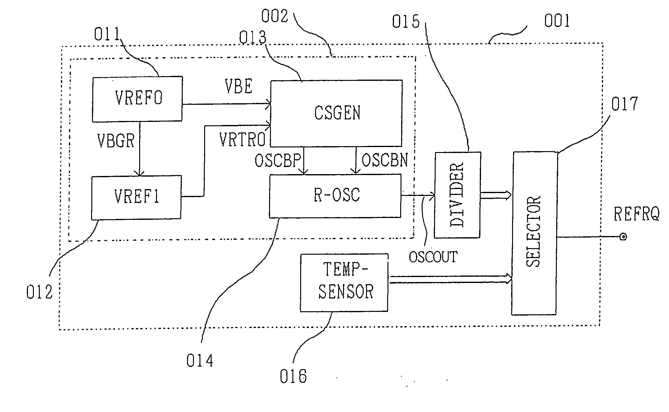
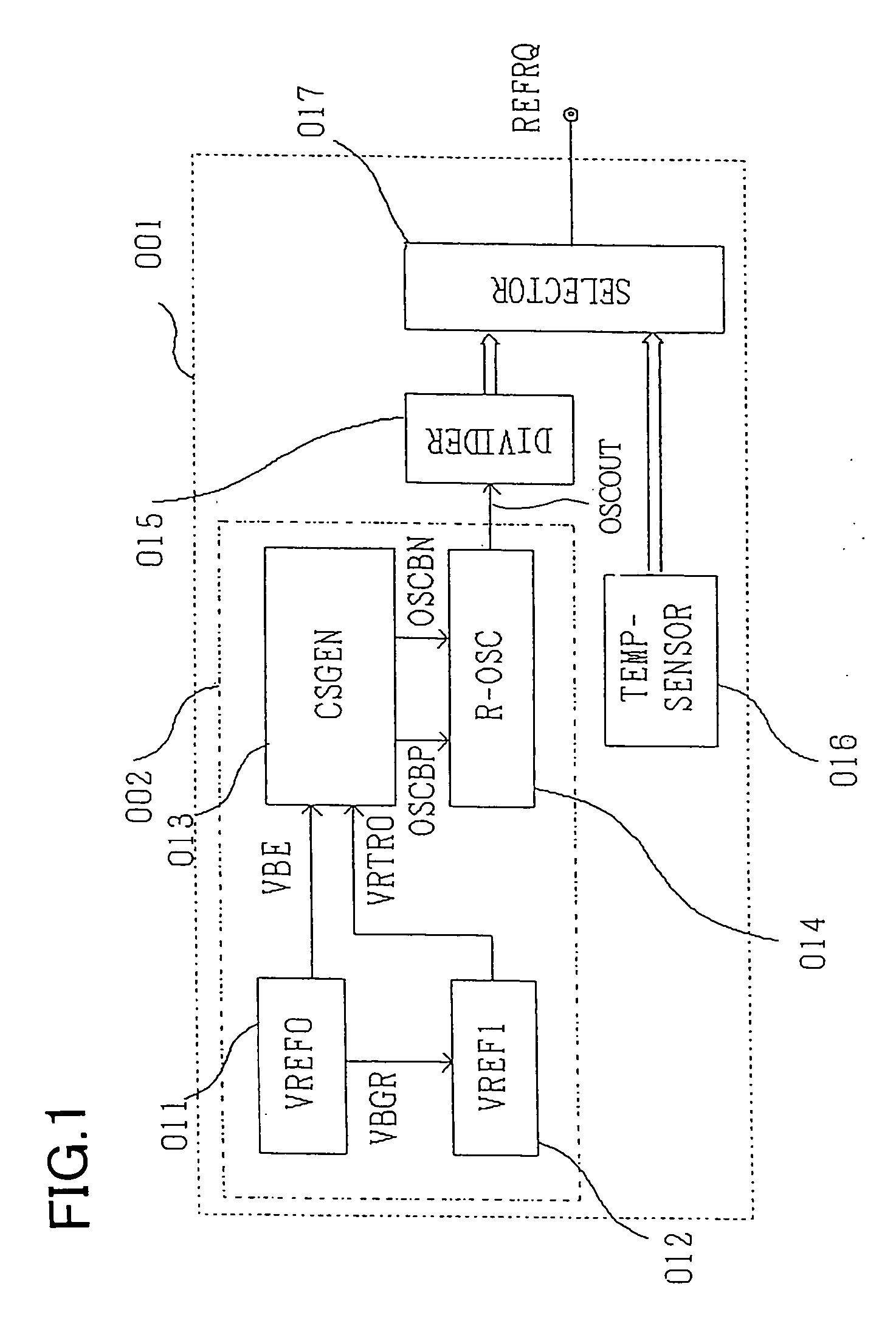
[0041] A preferred embodiment of the invention will specifically be described below with reference to accompanying drawings. FIG. 1 illustrates a configuration of a refresh period generating circuit of this embodiment. A refresh period generating circuit 001 as shown in FIG. 1 is provided with an oscillation circuit 002 such that the oscillating frequency has analog-form temperature dependence, a dividing circuit (DIVIDER) 015, a temperature sensor (TEMP-SENSOR) 016 and a frequency selector (SELECTOR) 017. The refresh period generating circuit 001 outputs a refresh reference signal REFRQ that is a reference of refresh of the DRAM cell.

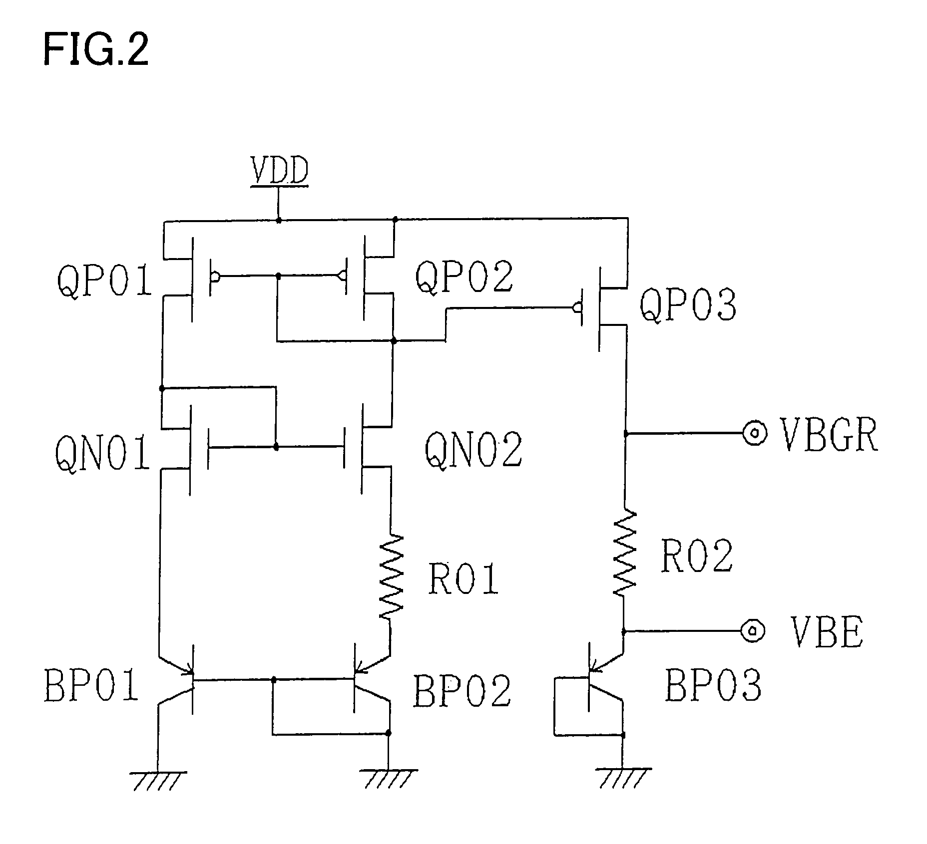
[0042] The analog oscillation circuit 002 basically has the same configuration as in FIG. 9, and is comprised of a band-gap type reference voltage generating circuit (VREF0) 011, a comparative voltage generating circuit (VREF1) 012, a current control signal generating circuit (CSGEN) 013 with positive temperature dependence, and a ring oscillator (R-O...


PUM


Abstract

A refresh period generating circuit which generates a refresh period in refreshing a DRAM cell, comprising: an oscillation circuit which oscillates at a frequency with temperature dependence on ambient temperature; a dividing circuit which divides an oscillation output of the oscillation circuit; a temperature detector which detects the ambient temperature; and a selector which switches and selects among division outputs with respective frequencies from the dividing circuit based on an output of the temperature detector, and outputs a signal as a reference of the refresh period. The temperature dependence in the oscillation circuit includes a positive temperature coefficient in a predetermined temperature range, and does not include a positive temperature coefficient out of the predetermined temperature range. The selector switches the division outputs out of the predetermined temperature range.

Description

BACKGROUND OF THE INVENTION [0001] 1. Field of the Invention [0002] The present invention relates to a refresh period generating circuit for generating a refresh period in a DRAM product (for example, including general-purpose DRAM, SDRAM, pseudo SRAM, and system LSI installed with DRAM) having the auto refresh function on a memory cell (hereinafter, referred to as a DRAM cell) of DRAM (Dynamic Random Access Memory). [0003] 2. Related Art [0004] A DRAM cell is comprised of a capacitor that stores an electrical charge as data and a transistor that switches between input and output of the data. The data retention characteristics of the DRAM cell have extremely large temperature dependence as compared with electrical characteristics of other structural elements such as, for example, a MOS transistor. The electrical characteristics of other structural elements are generally dependent on the temperature dependence of the mobility of electrons. It is known that an increase in temperature ...

Claims


Application Information

Patent Timeline
IPC IPC(8): G11C7/00
CPCG11C7/04G11C11/406G11C2211/4065G11C11/40626G11C11/40615
Inventor ITO, YUTAKAODAIRA, NOBUHIRO
Owner LONGITUDE LICENSING LTD
Why Eureka
Try Eureka