Luminescent compounds with carbene ligands

a carbene ligand and carbene metal technology, applied in the direction of discharge tube/lamp details, indium organic compounds, natural mineral layered products, etc., can solve the problems of not being sufficiently stable for commercial devices, using carbene ligands as electroluminescent compounds, and not well known photochemistry applications of carbene ligands

Active Publication Date: 2006-02-02
SOUTHERN CALIFORNIA THE UNIV OF +1
View PDF5 Cites 109 Cited by
  • Summary
  • Abstract
  • Description
  • Claims
  • Application Information

AI Technical Summary

Benefits of technology

[0011] In addition, existing compounds do not include compounds that are stable emitters for high energy spectra, such as a blue spectra. An object of the invention is to provide a class of organic emissive compounds that can emit light with various spectra, including high energy spectra such as blue, in a stable manner.

Problems solved by technology

However, applications of carbene ligands are not well known in photochemistry and have yet to be used as electroluminescent compounds.
One issue with many existing organic electroluminescent compounds is that they are not sufficiently stable for use in commercial devices.
In addition, existing compounds do not include compounds that are stable emitters for high energy spectra, such as a blue spectra.

Method used


Image

  • Luminescent compounds with carbene ligands
  • Luminescent compounds with carbene ligands
  • Luminescent compounds with carbene ligands

Examples


example 1

Synthesis of 1-phenyl-3-methylimidazolate iodide

[0395] 1-phenyl-3-methylimidazolate iodide was synthesized using the modified Ullmann coupling reaction described above. 1H NMR (250 MHz, CDCl3), ppm: 10.28 (s, 1H), 7.77-7.70 (m, 4H), 7.56-7.46 (m, 3H), 4.21 (s, 3H).

example 2

Synthesis of 1-Phenyl-3-methyl-benzimidazolate iodide

[0396] In the dark, an oven-dried 50 ml round-bottomed flask containing a stir bar was charged with CuI (0.171 g, 0.1 eq.), benzimidazole (1.273 g, 1.2 eq.), and cesium carbonate (6.138 g, 2.1 eq.) respectively. The round-bottomed flask with the contents was sealed with septa and degassed with argon for 15 minutes. Iodobenzene (1 ml, 1 eq.), 1,10-Phenanthroline (0.323 g, 0.2 eq.), and dimethylformamide (25 ml) were then successively added into the round-bottomed flask under a continuous flow of argon. The reaction mixture was degassed with argon for 30 minutes. The reaction was stirred with heating via an oil bath at 110° C. for 24 hours in the dark under nitrogen. The reaction mixture was cooled to ambient temperature and concentrated in vacuo. 10 ml of ethyl acetate was added into the concentrated reaction mixture. It was then filtered and washed with 30 ml of ethyl acetate. The filtrate was concentrated under vacuo to give the...

example 3

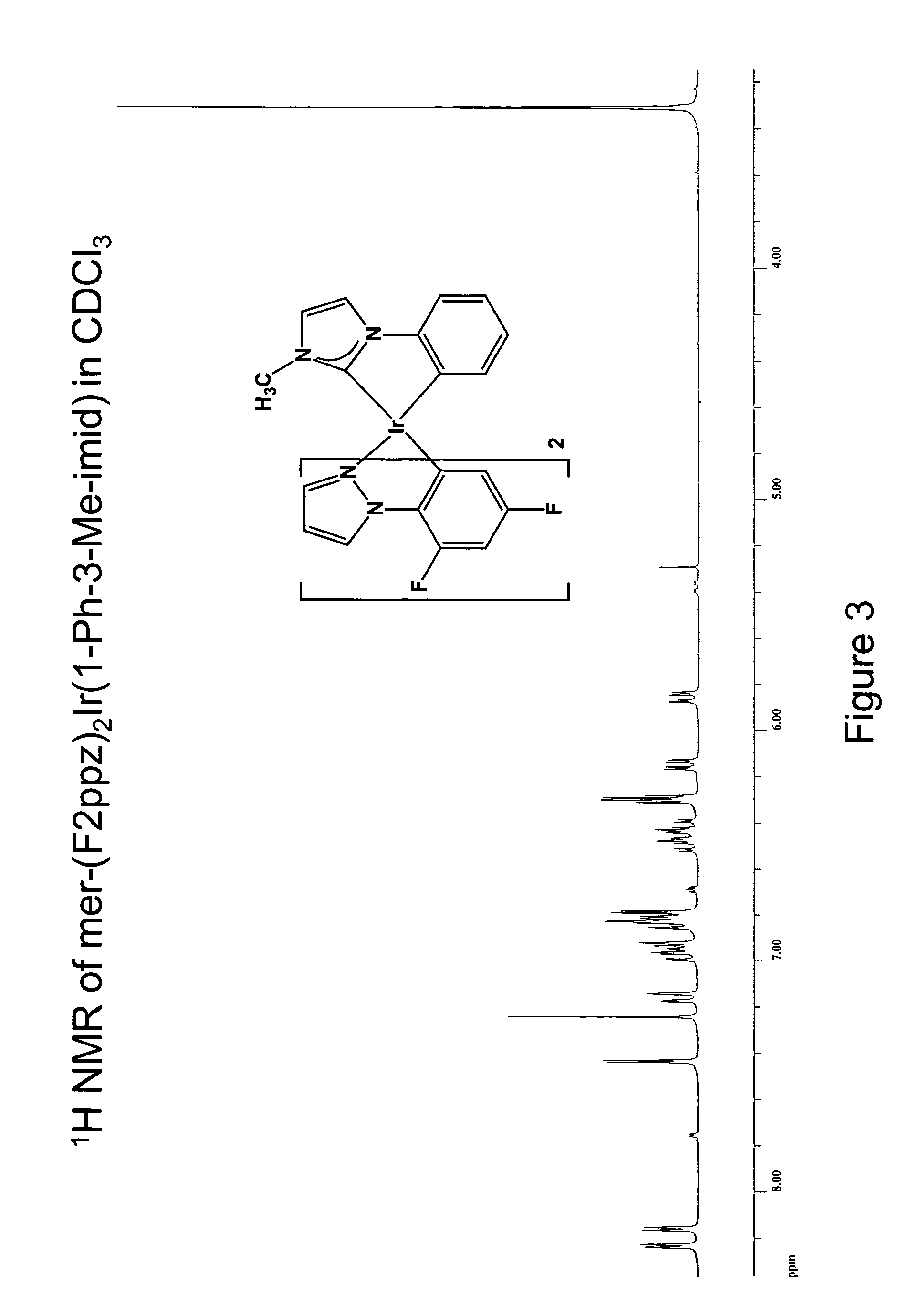
Synthesis of mer-iridium(III) bis[(2-(4′,6′-difluorophenyl)-2-pyrazolinato-N,C2′)] (1-phenyl-3-methyl-imidazolin-2-ylidene-C,C2′)

[0398] A 25 ml round-bottomed flask was charged with 0.014 g of silver(I) oxide, 0.030 g of 1-phenyl-3-methyl-imidazolate iodide, 0.062 g of [(F2ppz)2IrCl]2, and 15 ml of 1,2-dichloroethane. The reaction was stirred and heated with an oil bath at 77° C. for 15 hours in the dark under nitrogen while protected from light with aluminum foil. The reaction mixture was cooled to ambient temperature and concentrated under reduced pressure. Filtration through Celite using dichloromethane as the eluent was performed to remove the silver(I) salts. A light yellow solution was obtained and addition of methanol gave 0.025 g (30% yield) of iridium complex as a colorless solid.

[0399]1H NMR (500 MHz, CDCl3), ppm: 8.24 (d, 1H, J=2.8 Hz), 8.16 (d, 1H, J=2.8 Hz), 7.43 (d, 1H, J=1.9 Hz), 7.15 (d, 1H, J=7.5 Hz), 6.96 (ddd, 1H, J =7.5, 7.0, 1.9 Hz), 6.93 (dd, 1H, J=7.0, 1.9 H...


PUM


Abstract

An organic light emitting device is provided. The device has an anode, a cathode and an organic layer disposed between the anode and the cathode. The organic layer comprises a compound further comprising one or more carbene ligands coordinated to a metal center.

Description

[0001] This application is a continuation-in-part of U.S. application No. ______, filed May 18, 2004, entitled Luminescent Compounds with Carbene Ligands, and which is incorporated by reference in its entirety.FIELD OF THE INVENTION [0002] The present invention relates to organic light emitting devices (OLEDs), and more specifically to phosphorescent organic materials used in such devices. More specifically, the present invention relates to carbene-metal complexes incorporated into OLEDs. BACKGROUND [0003] Opto-electronic devices that make use of organic materials are becoming increasingly desirable for a number of reasons. Many of the materials used to make such devices are relatively inexpensive, so organic opto-electronic devices have the potential for cost advantages over inorganic devices. In addition, the inherent properties of organic materials, such as their flexibility, may make them well suited for particular applications such as fabrication on a flexible substrate. Exampl...

Claims


Application Information

Patent Timeline
Patent Type & Authority Applications(United States)
IPC IPC(8): H05B33/14C09K11/06C07F15/00H01L51/00H01L51/50
CPCC07F15/0033C07F15/0086C09K11/06C09K2211/1011C09K2211/1029C09K2211/1044C09K2211/1048C09K2211/1051C09K2211/1059C09K2211/1074C09K2211/1088C09K2211/1092C09K2211/1096C09K2211/185H05B33/14Y10S428/917H10K85/341H10K85/348H10K85/346H10K85/342H10K50/11H10K2101/10
Inventor THOMPSON, MARK
Owner SOUTHERN CALIFORNIA THE UNIV OF
Why Eureka
Try Eureka