Electrically conductive textile

a technology of electrically conductive textiles and textiles, applied in the direction of conductive pattern formation, conductive chairs, transportation and packaging, etc., can solve the problems of reducing the robustness or durability of the conductive textile application, reducing the contact point, and substantially limiting the material selection of the strands, so as to achieve stable solder connection and increase the robustness of the connection

Active Publication Date: 2006-02-09
GENTHERM GMBH
View PDF8 Cites 19 Cited by
  • Summary
  • Abstract
  • Description
  • Claims
  • Application Information

AI Technical Summary

Benefits of technology

[0013] One method of forming the inventive surface structure includes providing an electrically conductively coated surface structure such as metallized fabric. A contact zone is created in the region wherein it is desired to attach a connecting conductor. In one example, a thickened contact zone is provided by galvanizing the electrically conductively coating in the desired region. Thereafter, soldering the connecting conductor in the region of the contact zone results in a robust, flat, connection between the fabric and the connecting conductor. The robustness of the connection can be increased by additionally gluing the solder connection.
[0014] The present invention permits the soldering on of electrical conductors onto electrically conductively coated surface structures, even though it would typically be expected that, for example, a surface structure would be singed at soldering temperature. By way of the targeted, spatially limited reinforcement of the metallic coating within the connecting area of the conductive surface structure, i.e. by galvanizing processes, it is possible to create a stable solder connection in that area. In this manner, the present invention enables a flat, fatigue-endurable, robust connection.

Problems solved by technology

However, these attachment methods often cause a thickening at the contact point which is undesirable for some applications.
Such attachment methods can also create potential fatigue or stress points which can diminish the robustness or durability of the conductive textile application.
The unique nature of the composite material, however, substantially limits the material selection of the strands.
In the process, however, the textile carrier structure is destroyed in the surrounding area before or during the soldering process.
Other known heating elements have similar drawbacks in terms of contact attachment or limited material selection for the textile material.
In this case, however, a limitation of the material selection also exists.
Metallic coatings applied on conductive textiles are often extremely thin, such as for reasons of costs, weight, or flexibility (i.e. smaller than 1 μm).
In such a case, the conductive textiles can no longer be sufficiently contacted by means of a solder connection to insure the integrity of the material and durability of the connection.

Method used


Image

  • Electrically conductive textile
  • Electrically conductive textile
  • Electrically conductive textile

Examples


Embodiment Construction

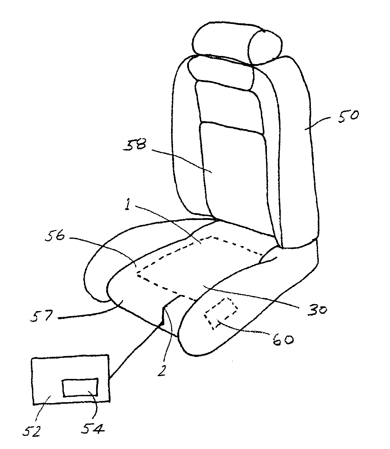
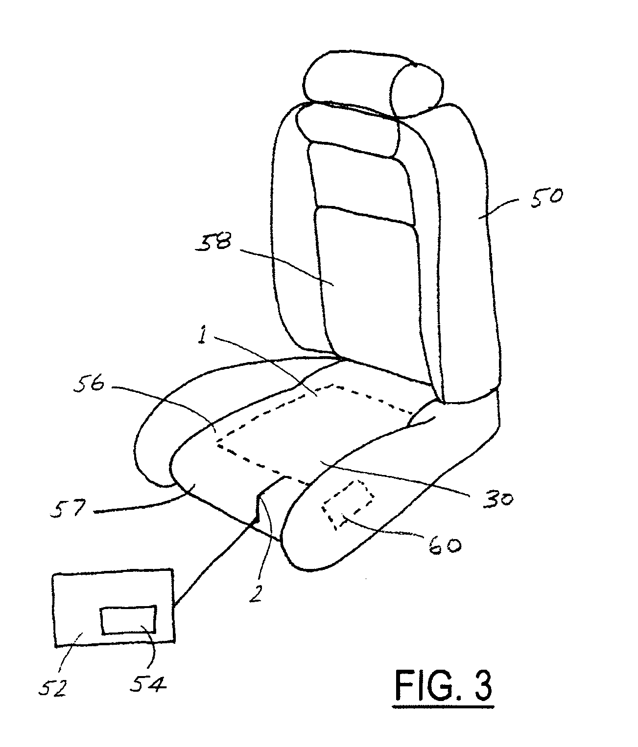
[0021] In the following figures, the same reference numerals are used to refer to the same components. While the present invention is described as an electrically conductively coated surface structure which can be used as part of a heating element for use within a vehicle seating system, it may be adapted and applied to various systems including steering wheel systems or other vehicle or non-vehicle systems requiring a heated surface. It an also be used in any conductive textile application including vehicle seat occupancy detection sensors. In this regard, in the following description, various operating parameters and components are described for several constructed embodiments. These specific parameters and components are included as examples only and are not meant to be limiting.

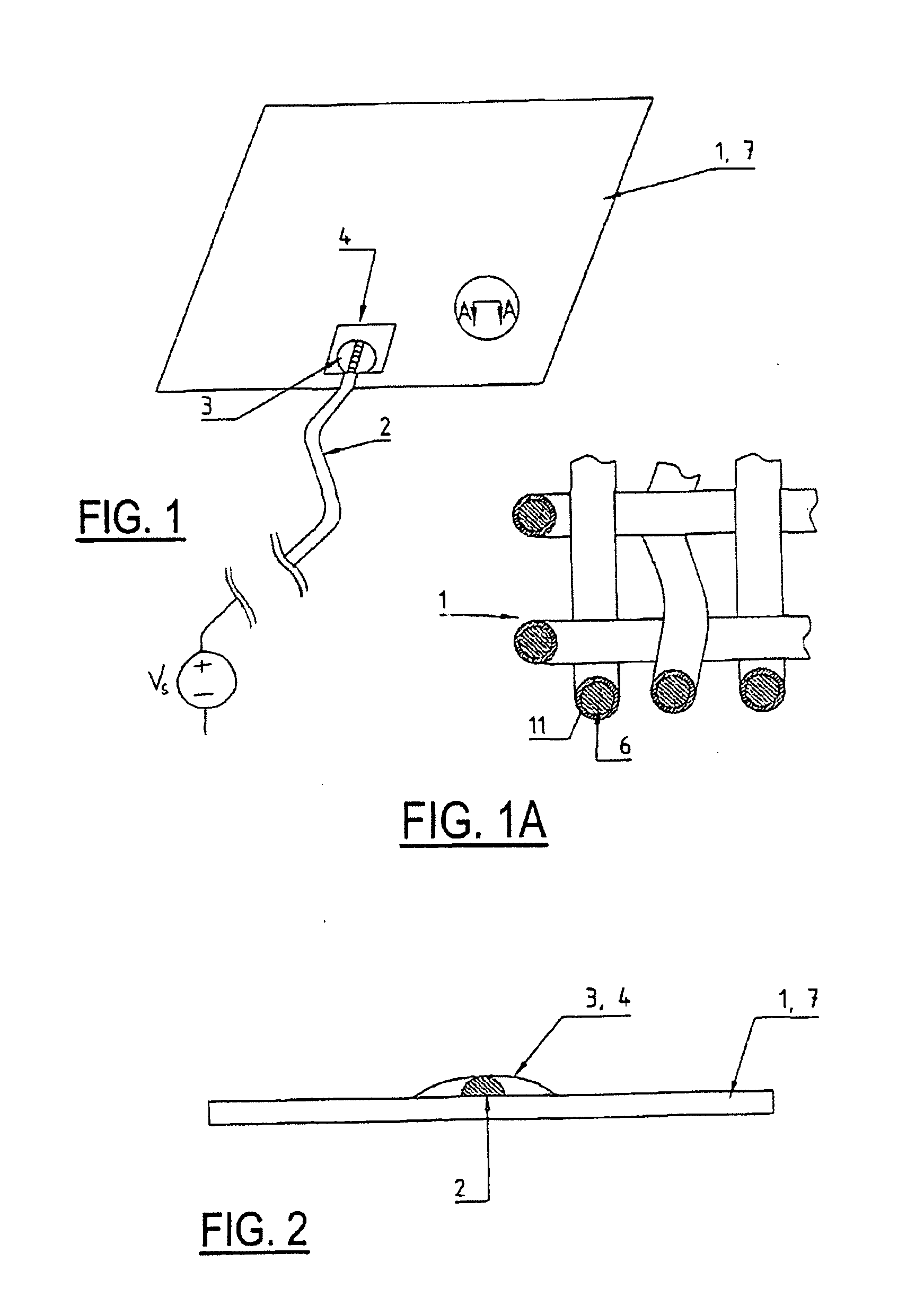
[0022]FIGS. 1, 1A and 2 show an electrically conductively coated surface structure. In the present case it is a metallized fabric. For example, the fabric comprises non-conductive synthetic strands which...


PUM

PropertyMeasurementUnit
thicknessaaaaaaaaaa
thicknessaaaaaaaaaa
thicknessaaaaaaaaaa

Abstract

A surface structure (1) that is at least partially electrically conductively coated by a conductor coating (11), and which can be connected to an electric power source by at least one electric connecting conductor (2). The connecting conductor (2) electrically contacts the conductor coating (11) at at least one solder point (3), and the conductive coating (11) is thickened at least at one contact zone (4) in the area of the solder point (3) as opposed to other areas (7) of the surface structure (1).

Description

TECHNICAL FIELD [0001] The present invention relates to an electrically conductive textile and, more particularly concerns a conductive textile suitable, for example, as an electric heating element, or for a vehicle seat-occupancy detection sensor. BACKGROUND OF THE INVENTION [0002] Electrically conductive textiles are usually brought into contact with electric cables or leads by means of crimping, sewing, or gluing. However, these attachment methods often cause a thickening at the contact point which is undesirable for some applications. Such attachment methods can also create potential fatigue or stress points which can diminish the robustness or durability of the conductive textile application. [0003] A composite material is known from DE 199 26 379, in which strands capable of soldering can be jacketed with a binder made of solder. The unique nature of the composite material, however, substantially limits the material selection of the strands. [0004] Various conductive textiles ...

Claims


Application Information

Patent Timeline
Patent Type & Authority Applications(United States)
IPC IPC(8): H05B1/00A47C7/72H05K3/34
CPCH05B3/34H05B2203/013H05B2203/029H05K3/10H05K3/244Y10T29/49179H05K2201/029H05K2201/0367H05K2201/09736Y10T29/49144H05K3/3405B60N2/002B60N2/5685
Inventor KROBOK, MARTINVOELK, MARKUSBRAMBERGER, PETER
Owner GENTHERM GMBH
Why Eureka
Try Eureka