Method and device for creating a micro plasma jet

a plasma jet and micro-plasma technology, applied in plasma techniques, gas-filled discharge tubes, manufacturing tools, etc., can solve the problems of micro-beam generators that are often limited in size, affecting scalability and power consumption, electrode wear, etc., to reduce the likelihood of arcing, inhibit local increases in electron density, and operation is simple

Active Publication Date: 2006-02-09
MOHAMED ABDEL ALEAM H +2
View PDF38 Cites 55 Cited by
  • Summary
  • Abstract
  • Description
  • Claims
  • Application Information

AI Technical Summary

Benefits of technology

[0015] MHCDs are high-pressure gas discharges in which the hollow cathode is formed by a microhollow structure, as described in U.S. Pat. No. 6,433,480 to Stark et al., which is hereby incorporated by reference. Hollow cathode discharges are very stable, in part due to a “virtual anode” that is created across the hollow. This virtual anode inhibits local increases in electron density by a corresponding reduction in voltage, reducing the likelihood of arcing. Further, the present invention may be operated with a direct current (DC) voltage on the order of hundreds of volts (up to approximately 1000V), which renders its operation simpler than devices relying on RF or microwave signals.

Problems solved by technology

Devices that attempt to generate discharges at higher or atmospheric pressures face problems with heating and arcing within the gas and / or the electrode, sometimes leading to problems with electrode wear.
However, these adjustments can affect scalability and power consumption.
In general, micro beam generators are often limited in size by a requirement that the concentric or coaxial dielectric be limited in thickness for proper plasma generation.
Further, the above high pressure devices require RF or microwave signals, which can complicate practical implementation.

Method used


Image

  • Method and device for creating a micro plasma jet
  • Method and device for creating a micro plasma jet
  • Method and device for creating a micro plasma jet

Examples


Embodiment Construction

[0024] The following detailed description is an example of an embodiment in the best presently contemplated modes of carrying out the invention. This description is not to be taken in a limiting sense, but is made merely for the purpose of illustrating general principles of embodiments of the invention.

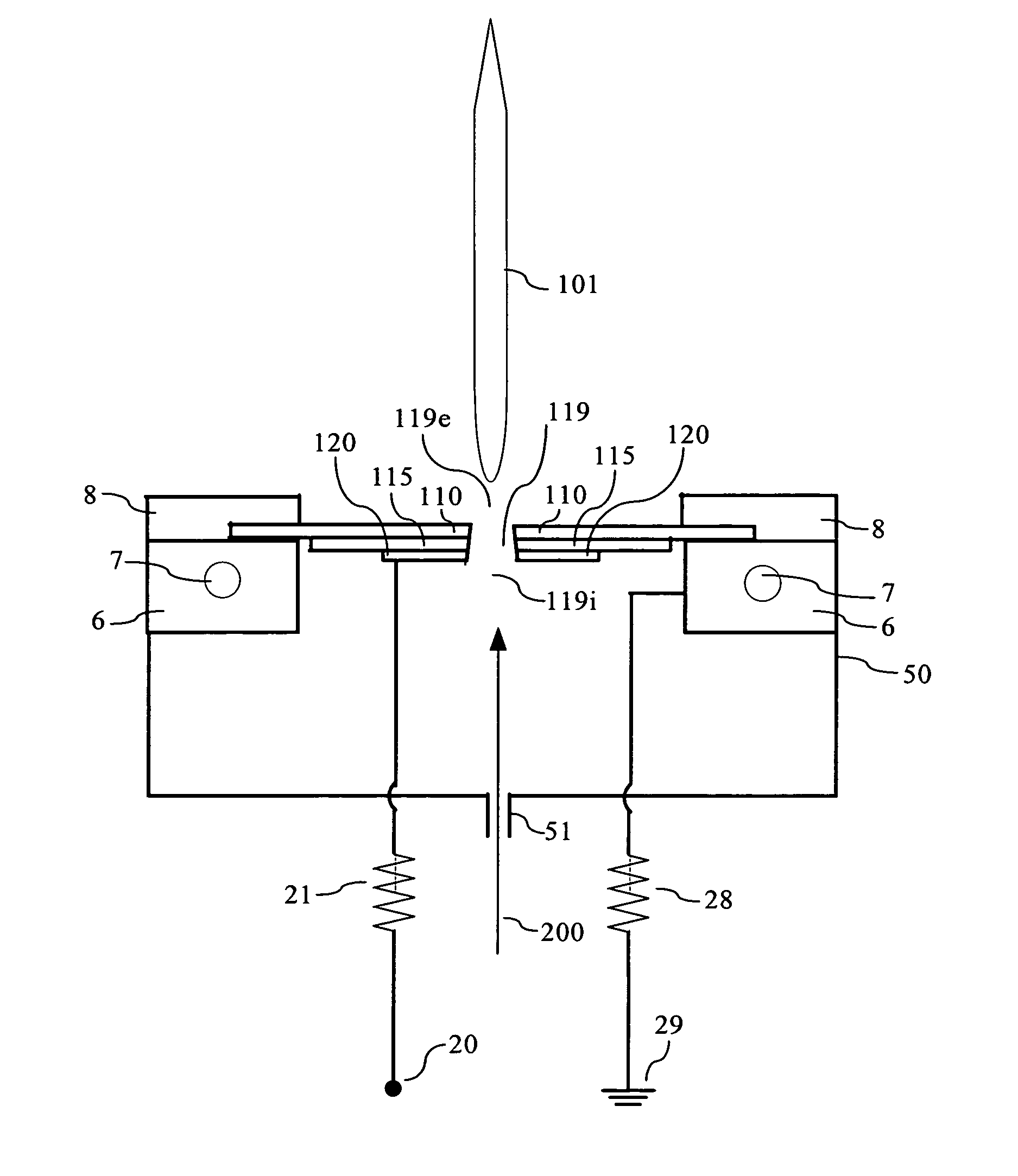
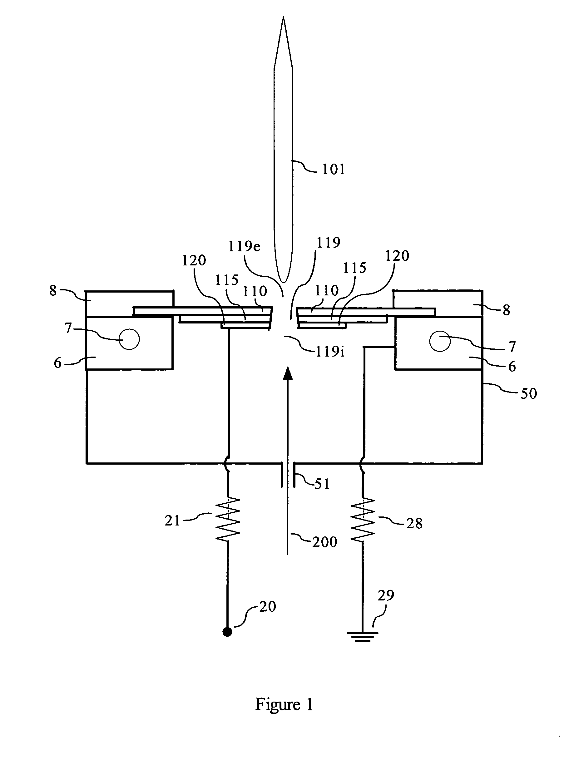
[0025] The present invention is an apparatus for the creation of an atmospheric pressure, low temperature plasma micro jet. In addition, radical species of the present invention may be controlled or tuned for specific applications. By operation with different gases, the device is a simple plasma-reactor producing particular radicals, such as ozone, OH, or other reaction products, depending on the desired gas.

[0026] The micro jet of the present invention is based on inducing a glow discharge in an axial and lateral direction while flowing air or other gases through a microhollow gas passage subject to an electric field. The jet may be operated in parallel with similar such jets for s...


PUM

PropertyMeasurementUnit
temperaturesaaaaaaaaaa
pressureaaaaaaaaaa
DC) voltageaaaaaaaaaa

Abstract

A microhollow cathode discharge assembly capable of generating a low temperature, atmospheric pressure plasma micro jet is disclosed. The microhollow assembly has at two electrodes: an anode and a cathode separated by a dielectric. A microhollow gas passage is disposed through the three layers, preferably in a taper such that the area at the anode is larger than the area at the cathode. When a potential is placed across the electrodes and a gas is directed through the gas passage into the anode and out the cathode, along the tapered direction, then a low temperature micro plasma jet can be created at atmospheric pressure.

Description

CROSS-REFERENCE TO RELATED APPLICATION [0001] The present application claims priority from U.S. Provisional Application Ser. No. 60 / 575,146, filed May 28, 2004.STATEMENT REGARDING GOVERNMENT SUPPORT [0002] This invention was made in part with government support under Grant No. AFOSR F49620-00-1-0079 awarded May 1, 2000 by the Air Force Office of Scientific Research. The government has certain rights in this invention.BACKGROUND OF THE INVENTION [0003] 1. Field of the Invention [0004] The present invention relates generally to the field of plasma devices and their uses. More particularly, this invention relates to the creation and use of a microhollow cathode plasma jet discharge. [0005] 2. Description of the Related Art [0006] Plasma is an electrically neutral, ionized state of gas, which is composed of ions, free electrons, and neutral species. As opposed to normal gases, with plasma some or all of the electrons in the outer atomic orbits have been separated from the atom, producin...

Claims


Application Information

Patent Timeline
Patent Type & Authority Applications(United States)
IPC IPC(8): H01J7/24
CPCH05H1/24H05H1/2406
Inventor MOHAMED, ABDEL-ALEAM H.KOLB, JUERGEN FRIEDRICHSCHOENBACH, KARL H.
Owner MOHAMED ABDEL ALEAM H
Why Eureka
Try Eureka