
Developing apparatus
a technology of developing apparatus and development apparatus, which is applied in the direction of electrographic process apparatus, instruments, developers, etc., can solve the problems of increasing image density, uneven image density, and reducing image density in solid image portions, so as to prolong life
Patent Information
- Authority / Receiving Office
- US · United States
- Current Assignee / Owner
- Publication Date
- 2006-02-09
- Estimated Expiration
- Not applicable · inactive patent
Smart Images
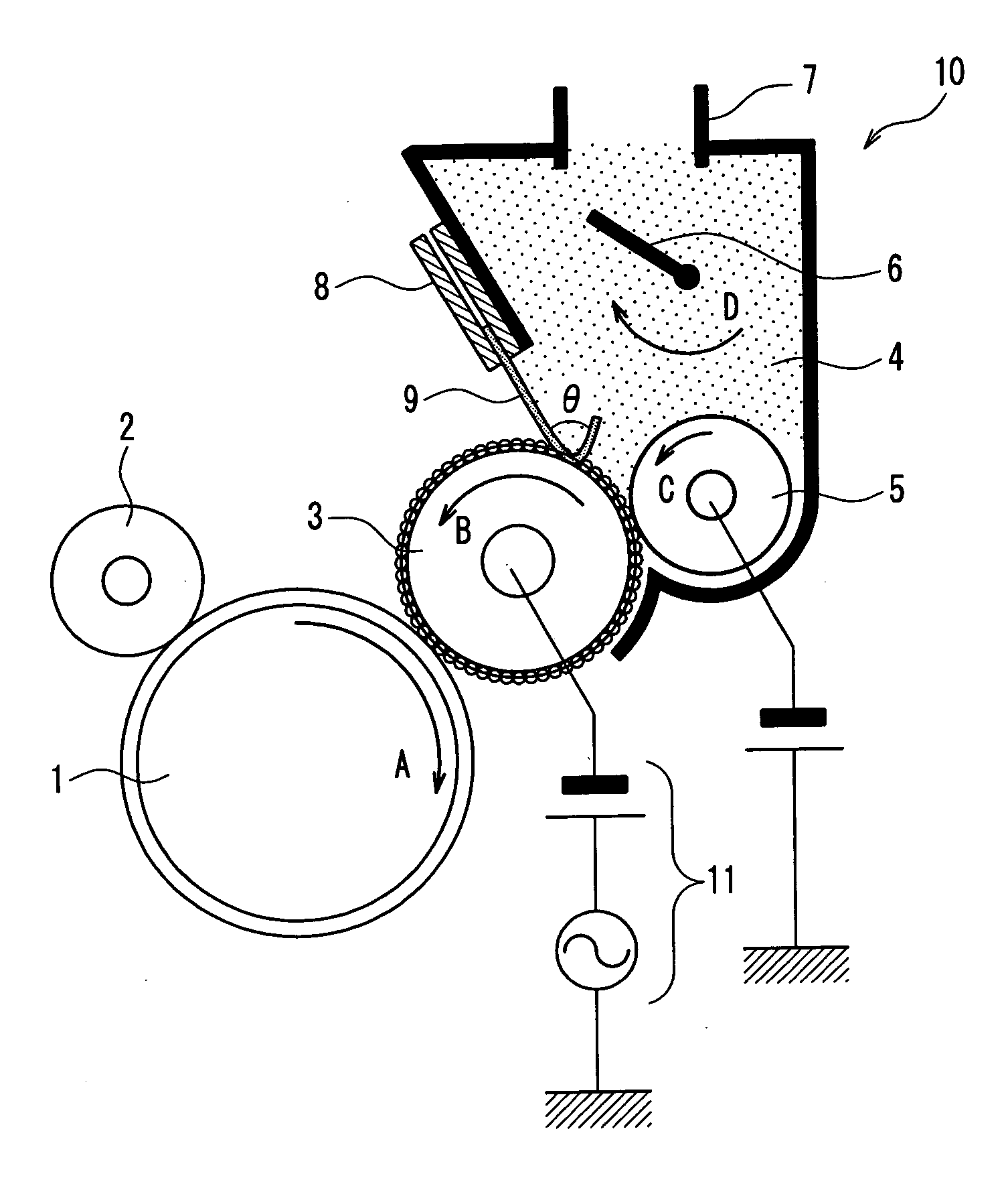
Figure 1 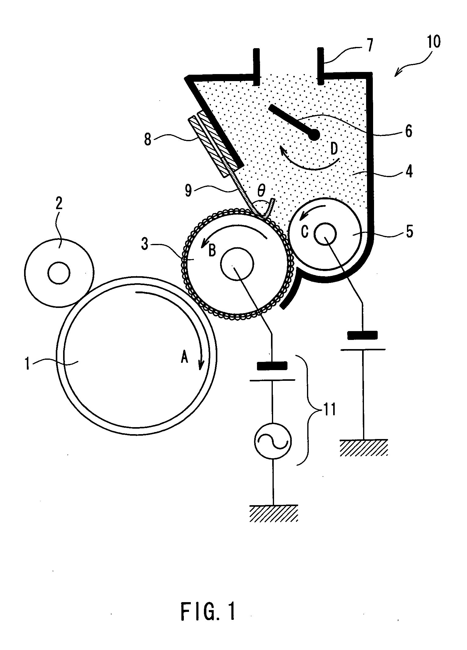
Figure 2 
Figure 3
Abstract
Description
BACKGROUND OF THE INVENTION
[0001] 1. Field of the Invention
[0002] The present invention relates to developing apparatuses for electrophotographic image forming apparatuses used in copiers, printers, facsimiles, and machines that combine these functions. In particular, the present invention relates to one-component type developing apparatuses in which a spherical toner is formed into a layer on a toner holding member and, in a development region, the spherical toner is developed onto an electrostatic latent image holding member.
[0003] 2. Description of Related Art
[0004] In recent years, electrophotographic developing apparatuses can be classified roughly into one-component development systems in which only a toner is used and two-component development systems in which a toner and a carrier are used. In the one-component development systems, a toner is supplied from a toner supply member to a toner transporting (holding) member, and after the toner is formed into a thin layer by a...
Examples
embodiment 1
[0051] Embodiment 1 will be described with reference to Working Example 1. As an apparatus for image evaluation serving as Working Example 1, KX-CL500 (manufactured by Panasonic) whose developing apparatus part was modified was used. This machine operates at a processing speed of 100 mm / s and is capable of printing 16 sheets of A4 paper per minute. Various numerical values, materials, and so on that are given below as an example belong to this working example.
[0052]FIG. 1 is a cross-sectional view showing the principal part of a developing apparatus 10 according to Embodiment 1 of the present invention. The developing apparatus 10 is a one-component development type developing apparatus that uses a toner for rendering an electrostatic latent image visible.
[0053] A photosensitive drum 1, which is an electrostatic latent image holding member, is a layered organic photoreceptor. It has an outer diameter of 24 mm, and is made to rotate in a direction shown by the arrow A at a circumfe...
embodiment 2
[0119] In Embodiment 2, the conditions to which the surface of the development roller 3 was polished were changed. The surface roughness was Rz=2 μm in Working Example 1 described above, whereas the surface roughness was set to 3 μm in working Example 2, 5 μm in Working Example 3, 10 μm in Working Example 4, 15 μm in Working Example 5, 20 μm in Working Example 6, and 25 μm in Working Example 7. The average spacing S between local crests was set to 40 μm in all of these working examples. Regarding Working Examples 2 to 7, the same evaluation as that shown in Table 1 above was conducted. Table 2 below shows the evaluation results.
TABLE 2UnevennessAmountofSurfaceofLayerImageimageWhiteRoughneschargethicknessdensitydensityFoggingstripes / BlackRz(μm)(μC / g)(mg / cm2)(ID)(3σ)Δ %stripesWorking2Beginning−18.50.411.410.0520.5GoodEx. 1After−15.50.371.360.0790.9Good30,000sheetsWorking3Beginning−20.50.431.440.0450.3GoodEx. 2After−18.20.421.470.0550.6Good30,000sheetsWorking5Beginning−20.80.411.430....
embodiment 3
[0126] In Embodiment 3, Working Example 8 in which the surface roughness of the development roller Rz=5.0 μm and the average spacing S between local crests was 70 μm was produced. Table 3 below shows the evaluation results at the beginning and after 30,000 sheets.
TABLE 3UnevennessAmountofAverageofLayerImageimageWhiteSpacingchargethicknessdensitydensityFoggingstripes / BlackS(μm)(μC / g)(mg / cm2)(ID)(3σ)Δ %stripesWorking40Beginning−20.80.411.430.0420.3GoodEx. 3After−18.80.391.430.0510.5Good30,000sheetsWorking70Beginning−24.10.421.430.0350.2GoodEx. 8After−23.60.431.420.0320.2Good30,000sheets
[0127] From the results in Table 3, it is found that in Working Example 8, the amount of charge is improved more, fogging decreases more, and also unevenness of the density is improved more than in Working Examples 3 in which the average spacing S between local crests was 40 μm.
[0128] Furthermore, development rollers in which the average spacing S between local crests was set to 50, 70, 100, 120, 150...