Scanning microscope and laser microscope
- Summary
- Abstract
- Description
- Claims
- Application Information
AI Technical Summary
Benefits of technology
Problems solved by technology
Method used
Image

Examples
Embodiment Construction
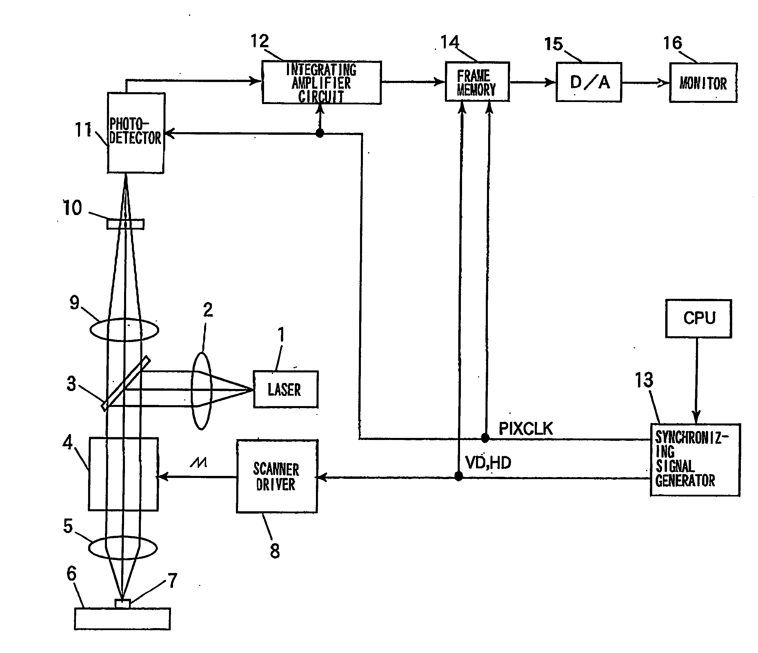
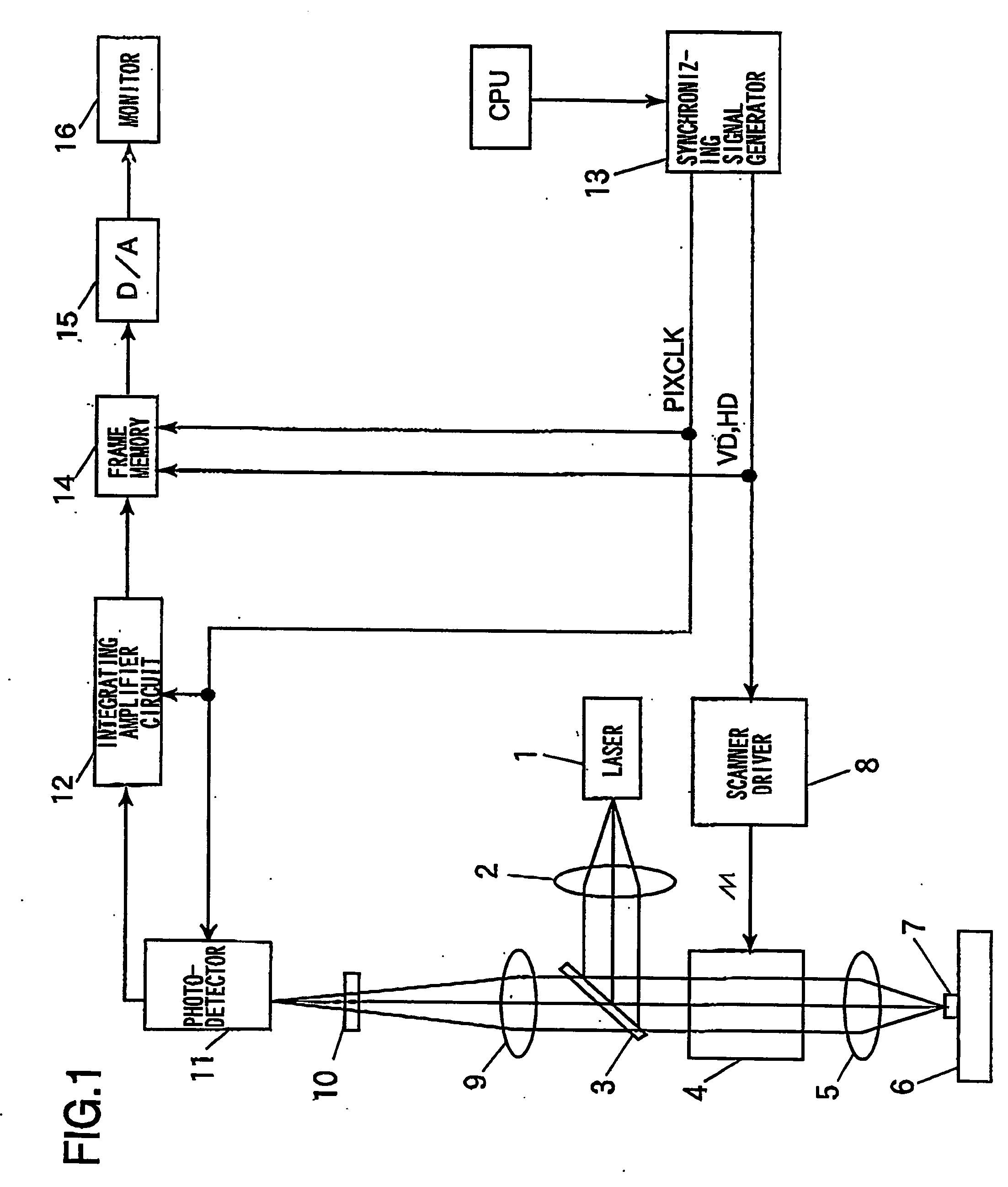
[0028]FIG. 1 shows a configuration of a scanning laser microscope according to an embodiment. Laser light emitted from a laser light source 1 passes through a collimator lens 2, thereby obtaining a parallel light flux. The parallel light flux thus obtained is reflected by a first dichroic mirror 3, and introduced to a two-dimensional scanning optical system 4. Furthermore, the laser light thus introduced passes through an objective lens 5, thereby forming a light spot on a fluorescent sample (or specimen) 7 mounted on an XY stage 6. Here, the two-dimensional scanning optical system 4 is formed of a pair of Galvano mirror scanners and so on, for example. The two-dimensional scanning optical system 4 having such a configuration has a function of scanning the light spot on the fluorescent sample 7 in the X-Y directions according to driving signals from a scanner driver 8.
[0029] Upon irradiating the spot light onto the fluorescent sample 7, fluorescence (or reflected light) is emitted ...
PUM
 Abstract
Description
Claims
Application Information
 - R&D
- Intellectual Property
- Life Sciences
- Materials
- Tech Scout
- Unparalleled Data Quality
- Higher Quality Content
- 60% Fewer Hallucinations
Browse by: Latest US Patents, China's latest patents, Technical Efficacy Thesaurus, Application Domain, Technology Topic, Popular Technical Reports.
© 2025 PatSnap. All rights reserved.Legal|Privacy policy|Modern Slavery Act Transparency Statement|Sitemap|About US| Contact US: help@patsnap.com