Autonomous ultra-short optical pulse compression, phase compensating and waveform shaping device

Inactive Publication Date: 2006-02-16
JAPAN SCI & TECH CORP
View PDF7 Cites 165 Cited by
  • Summary
  • Abstract
  • Description
  • Claims
  • Application Information

AI Technical Summary

Benefits of technology

[0018] The modified SPIDER device used in the apparatus of the present invention is modified from the conventional SPIDER device by forming a chirped light pulse not from the output light pulse but from another light pulsed source. As forming a chirped light pulse from another light pulsed source, the modified SPIDER device can by no means weaken the intensity of replica light pulses forming from the output light pulse. As this configuration can also enhance the intensity of a chirped light pulse, it becomes possible to heighten the contrast of an interference figure or image produced by the spectrometer from two frequency-mixed replica light pulses. Further, reading the interference figure by means of an ICCD allows all the spectral phases to be detected rapidly and at high sensitivity.
[0019] And, the ability of the modified SPIDER device to be able to detect rapidly all the spectral phases at high sensitivity permits a feedback device to feed differences between the detected phases and pre-established phases as the additive phase back to the spatial light m

Problems solved by technology

However, since the phase compensation by these methods is stationary and, if dynamic, is not autonomous, it can be only effective where the phases of the spectral components of a light pulse are known beforehand and also temporally constant.
However, since there need be a considerably large number of light pulse trains and a plenty of time before a phase determination is made, the method is found only efficient where the phases of the spectral components of a light pulse are temporally constant.
Thus, a problem in the prior art apparatus is that it has been necessary to use a light source only after determination is made in detail of phase information of a light pulse that the light source generates.
Further, such temporal fluctuations in phase if reduced by using a light source with a high degree of controllability have left the problem unresolved that the continuation time in which the ultrashort light pulse compression, phase compensation and waveform shaping can continuously be performed and accomplished is short, because of the unavoidable long-term fluctu

Method used


Image

  • Autonomous ultra-short optical pulse compression, phase compensating and waveform shaping device
  • Autonomous ultra-short optical pulse compression, phase compensating and waveform shaping device
  • Autonomous ultra-short optical pulse compression, phase compensating and waveform shaping device

Examples


Embodiment Construction

[0037] Hereinafter, the present invention will be described in detail with reference to certain suitable forms of implementation thereof illustrated in the drawing figures.

[0038] Referring first to FIGS. 1 and 2, an explanation is given in respect of the makeup of an autonomous ultrashort light pulse compression, phase compensation and waveform shaping apparatus according to the present invention as well as an operation thereof.

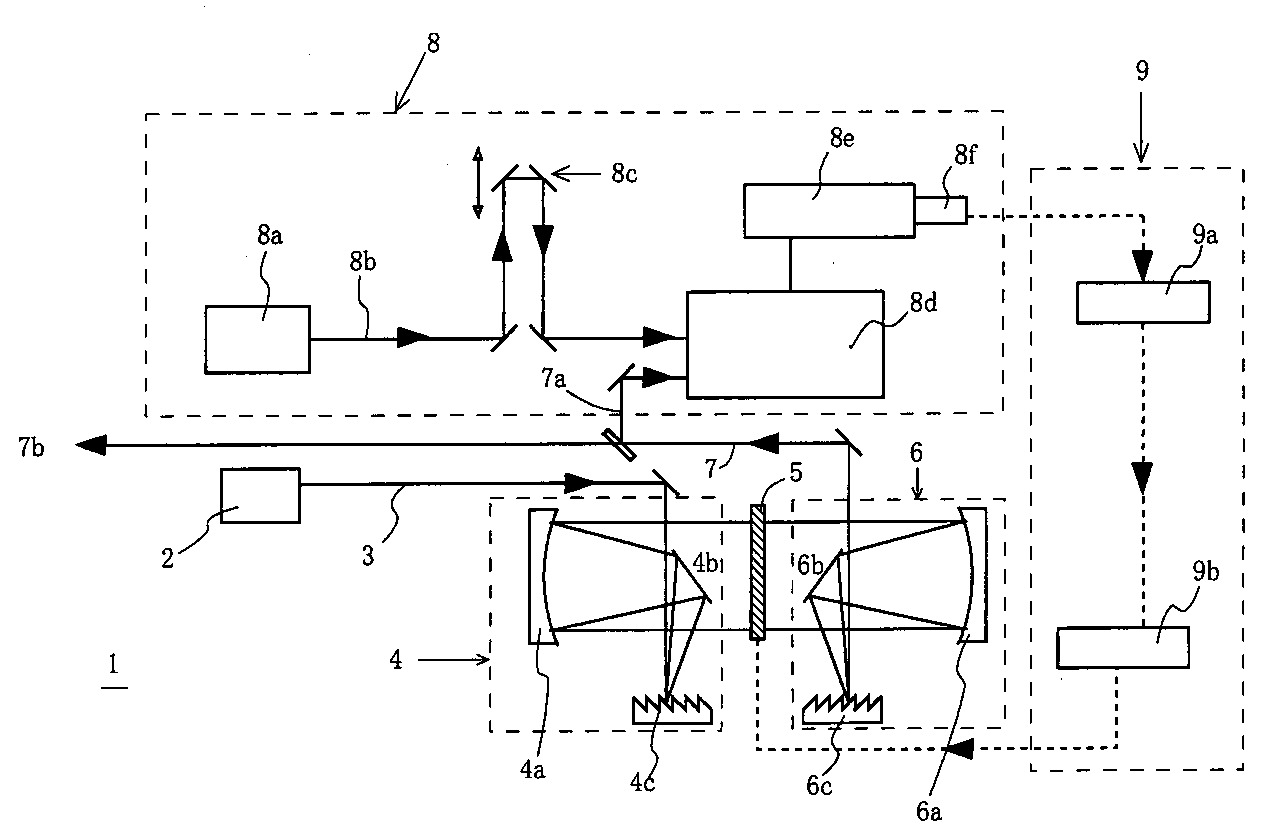
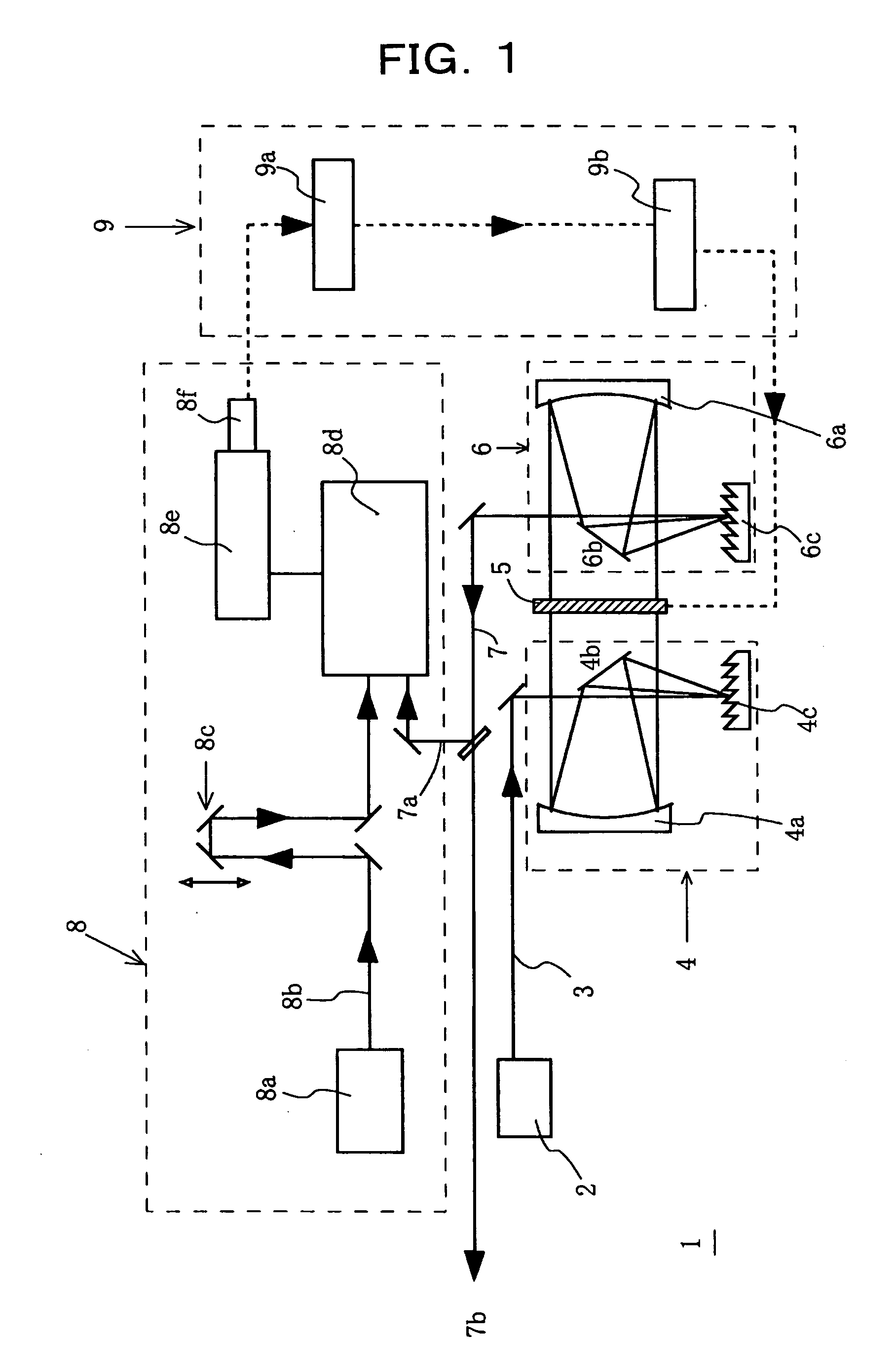
[0039]FIG. 1 is a diagram illustrating the makeup of an autonomous ultrashort light pulse compression, phase compensation and waveform shaping apparatus according to the present invention. As shown in the Figure, the autonomous ultrashort light pulse compression, phase compensation and waveform shaping apparatus designated by reference character 1 comprises a pulsed light source 2; a spectroscopic spatial dispersing device 4 for spatially dispersing a light pulse 3 emitted from the light source 2 into spectral components thereof; a spatial light modulator 5...


PUM


Abstract

Disclosed is an apparatus for autonomously compressing, phase-compensating and waveform-shaping an ultrashort light pulse that is fast and high in sensitivity in compensating for phase fluctuations and allows the use of a usual laser light source that is low in light intensity and has large temporal fluctuations in phase. The apparatus comprises: a pulsed light source (2); a spectroscopic spatial dispersing device (4) for spatially dispersing a light pulse (3) emitted from the pulsed light source (2) into spectral components thereof; a spatial light modulator (5) for adding a phase to each of the spectral components of the spatially dispersed light pulse (3); a multiplexer (6) for combining the phase added spectral components of the light pulse (3) together to form a composite output light pulse (7); a modified SPIDER device (8) for forming a spectral interference figure from a portion of the composite output light pulse (7); and a feedback device (9) for detecting a spectral phase from the spectral interference figure and feeding a signal representing a difference between the detected spectral phase and a pre-established phase back to the spatial light modulator (5). The modified SPIDER device (8) comprises: a pulsed light source for a chirped light pulse (8a); a delay unit (8c) for delaying a light pulse (8b) from the pulsed light source (8a) with an adjustable delay time; a dispersive medium (28) for forming a chirped light pulse (29) from the light pulse whose delay time is adjusted by the delay unit (8c); a replica pulse former (24) for forming from a portion of the output light pulse (7) a pair of replica light pulses (24a, 24b) one delayed after the other; a nonlinear optical crystal (31) for frequency-mixing the two replica pulses (24a, 24b) with the chirped light pulse (29); a spectrometer (8e) for forming an interference figure of the resultant two frequency-mixed replica light pulses; and an image reader (8f) for reading the interference figure of the two frequency-mixed replica light pulses.

Description

TECHNICAL FIELD [0001] The present invention relates to an autonomous ultrashort light pulse compression, phase compensation and waveform shaping apparatus in which use is made of a spatial light modulator for a phase compensation device indispensable to the generation of ultrashort light pulses in an ultrabroad band and of a modified SPIPER method as an improvement over the SPIDER method for determining the spectral phases of a light pulse generated. BACKGROUND ART [0002] The ultrashort light pulse compression technique, which allows realizing a minimum time duration that humankind can ever achieve, is yielding new discoveries and new technologies in so far unknown spheres of science with the use of ultrashort light pulses. Also, the ultrashort light pulse phase compensation technique with the ability to provide a train of light pulses with a controlled amount of phase compensation that varies with time commences being applied to various types of modulation spectroscopy and optical...

Claims


Application Information

Patent Timeline
IPC IPC(8): G01B9/02G02F1/35G02F1/37G02F1/01
CPCH04B10/508H04B10/503
Inventor HIRASAWA, MASAKATSUYAMASHITA, MIKIO
Owner JAPAN SCI & TECH CORP
Why Eureka
Try Eureka